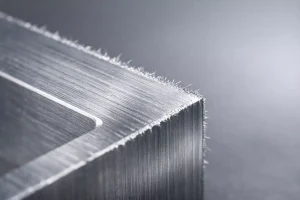

エンジニアリング製造や製品設計の分野では、表面の平坦度は美観だけでなく、組立精度や作業の安全性にも影響します。皿穴は、穴加工の基本的かつ重要な種類であり、その中核的価値は、ファスナーとワークピース表面のシームレスな統合を達成することにあります。
製品が工業規格に適合するためには、皿穴加工のプロセス仕様と応用技術をマスターすることが、すべてのエンジニアにとって不可欠な基礎となります。このテクニカルガイドでは、皿穴の定義から施工手順、一般的なトラブルシューティングまで、皿穴の包括的な概要を説明しています。
カウンターシンクホールとは?
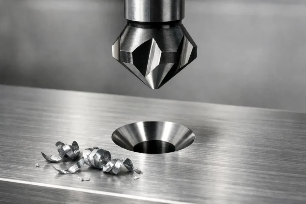
皿穴とは、ワークピースの既存の円筒形穴の開口部に加工された円錐形の拡大部を指す。その主な設計目的は、皿ネジ(マイナスネジ)用の凹んだ空間を提供することであり、ネジの頭が締め付けられた後、ワークピースの表面と同じ高さか、わずかに下に位置するようにすることである。
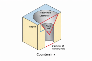
幾何学的な観点から見ると、標準的な皿穴は2つの部分で構成されています:下部の円筒形のパイロット穴と上部の円錐形の凹部です。この構造は、外観の整頓性を向上させるだけでなく、突出したボルトの頭が物に引っ掛かったり、傷をつけたりするのを防ぎます。
逆シンク穴の開け方
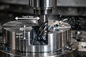
カウンターシンク穴の加工は、穴の直径を大きくする単純な問題ではなく、深さと角度を正確に制御する必要があるプロの切削工程です。穴が平らでネジにぴったり合うようにするには、以下の標準的な手順を踏むことをお勧めします:
パイロットホールの穴あけ
カウンターシンクを加工する前に、下穴を開けなければならない。下穴の直径は、ねじの呼びねじ径よりわずかに大きく、通常は0.2~0.5mm程度にする。下穴が傾いていると、その後の皿穴も傾いてしまい、ねじの頭が平らになりません。
カウンターシンクビットの選択と取り付け
カウンターシンクビットは、ねじの仕様と90度などの必要な角度に合ったものを選ぶ。ドリルプレスやハンドドリルにビットを装填する際は、軸の芯ずれによる穴形状の不揃いや多角形を防ぐため、必ず振れを確認してください。
深度制限の設定
精密加工や大量生産の場合は、ドリルプレスやビットにデプスストップを取り付けることをお勧めします。ハードウェア・リミットが利用できない場合は、まずスクラップ材でテストカットを行う。ねじが完全に同一平面に収まるのに必要な深さを測定し、複数の穴で一貫性が保たれるように送りスケールに印を付けます。
ドリリングとチップ除去の開始
ドリルを始動し、低速回転で切削を開始する。ショートストローク送りの原則に従い、一定の深さまで穴を開けてからビットを少し持ち上げる。これにより、円錐表面から切り屑を取り除くことができ、切り屑が穴壁に傷をつけたり、ビビリ跡がついたりするのを防ぐことができる。
検査と微調整
目標の深さに達したら、機械を停止し、ねじ穴にねじを入れて試 合します。理想的には、ネジの頭が表面から約0.1 mm下になるようにし、その後のコーティングや塗装の厚みを考慮する。深さが不十分な場合は、ドリルを再始動し、切込みをわずかに深くする。
カウンターシンク穴の種類
カウンターシンクの幾何学的プロファイルは、均一な荷重分布を確保するために、ファスナーのテーパーに正確に一致する必要があります。ファスナーの頭部形状や適用される技術規格により、一般的な皿穴の種類は以下の通りです:
ファスナーの規格と角度による分類
-
90° カウンターシンク:メートルファスナーの世界標準規格。
-
82° カウンターシンク:インペリアル(統一ねじ規格)ファスナーの代表的な仕様。
-
特殊アプリケーション・アングル:特定の技術要件に応じて、60°、100°、110°、120°などの角度も利用される。
エンジニアリング機能形態による分類
-
フラットヘッドカウンターシンク:最も広く使用されている形状で、上面が平らな円錐形の凹部を特徴とする。含まれる角度は通常、商業用金物(特に木工用)には82°、リベット打ちや特定の航空宇宙金物用途には100°が多い。
-
オーバルヘッドカウンターシンク:外形がわずかに凸状で滑らかな楕円頭ねじ用に特別に設計されています。含まれる角度は通常100°で、締結と美観の両方が要求されるモールディングやトリムなどの工業デザインで頻繁に使用されます。
-
ラウンドヘッドカウンターシンク:一般的ではありませんが、このタイプは丸頭ねじと効果的に組み合わされます。一般的には、デザイン上の特徴として、突出した装飾的なネジ頭が望まれる特殊なケースや、皿穴が元々備わっていないハードウェアにフラットプロファイルファスナーを取り付ける場合に使用されます。
カウンターシンクホールの寸法
技術図面では、はめあい精度を確保するために寸法仕様に厳密に従わなければなりません。以下は、ISO規格に基づく一般的なカウンターシンク寸法の参考表です:
平頭ファスナー用皿穴サイズ表(ISO)
すべての寸法は、カウンターシンクの角度を除いてミリメートル単位である。
データソース エンジニアのバイブル - ISO皿穴データ
| ファスナーサイズ(ネジ山) | パイロットホール径(クローズフィットH12) | パイロットホール径(ノーマルフィットH13) | パイロットホール径(ルーズフィットH14) | カウンターシンク径 | カウンターシンク角度 (°) |
| M3 | 3.2 | 3.4 | 3.6 | 6.94 | 90 |
| M3.5 | 3.7 | 3.9 | 4.2 | 8.96 | 90 |
| M4 | 4.3 | 4.5 | 4.8 | 9.18 | 90 |
| M5 | 5.3 | 5.5 | 5.8 | 11.47 | 90 |
| M6 | 6.4 | 6.6 | 7 | 13.71 | 90 |
| M8 | 8.4 | 9 | 10 | 18.25 | 90 |
| M10 | 10.5 | 11 | 12 | 22.73 | 90 |
| M12 | 13 | 13.5 | 14.5 | 27.21 | 90 |
| M16 | 17 | 17.5 | 18.5 | 33.99 | 90 |
| M20 | 21 | 22 | 24 | 40.71 | 90 |
82度マシンファスナー用皿穴サイズ表(ANSIインチ)
すべての寸法は、カウンターシンクの角度から離れたインチ単位である。
データソース エンジニアのバイブル - ANSI 82°皿穴データ
| ファスナーサイズ(ネジ山) | パイロットホール径(クローズフィット) | パイロットホール径(ノーマルフィット) | パイロットホール径(ルーズフィット) | カウンターシンク径 | カウンターシンク角度 |
| #0 | 1/15 | 6/79 | 3/32 | 5/42 | 82 |
| #1 | 3/37 | 4/45 | 8/77 | 13/89 | 82 |
| #2 | 3/32 | 7/69 | 7/62 | 16/93 | 82 |
| #3 | 5/47 | 8/69 | 9/70 | 1/5 | 82 |
| #4 | 3/25 | 9/70 | 14/97 | 9/40 | 82 |
| #5 | 9/64 | 5/32 | 11/64 | 25/99 | 82 |
| #6 | 2/13 | 10/59 | 5/27 | 12/43 | 82 |
| #8 | 9/50 | 10/51 | 13/61 | 1/3 | 82 |
| #10 | 15/73 | 21/95 | 5/21 | 5/13 | 82 |
| #12 | 15/64 | 15/61 | 6/23 | 39/89 | 82 |
| 1/4 | 17/64 | 9/32 | 19/64 | 36/71 | 82 |
| 5/16 | 21/64 | 11/32 | 23/64 | 40/63 | 82 |
| 3/8 | 25/64 | 13/32 | 27/64 | 16/21 | 82 |
| 7/16 | 29/64 | 15/32 | 31/64 | 69/85 | 82 |
| 1/2 | 17/32 | 9/16 | 39/64 | 7/8 | 82 |
| 9/16 | 19/32 | 5/8 | 43/64 | 1 | 82 |
| 5/8 | 21/32 | 11/16 | 47/64 | 1 1/8 | 82 |
| 3/4 | 25/32 | 13/16 | 29/32 | 1 3/8 | 82 |
カウンターシンクホールの用途と使用法
カウンターシンク設計は、表面品質やスペースの利用が厳しく要求される場面で広く利用されている、
および流体力学。主な用途は以下の通り:
表面平滑性の維持と流体力学
絶対的な表面平坦性が要求される構造部品(高速車両のアウタースキンなど)では、皿穴によりファスナーが表面の連続性を乱さないようにします。これにより、流体抵抗を効果的に低減し、高速運転中の乱流や空力ノイズを防止します。
機械的干渉の防止とスペースの最適化
精密アセンブリーやコンパクトな機械構造では、ファスナーヘッドを基板内に埋め込むことにより、表面の突起をなくします。これにより、可動部品間の物理的な干渉を防ぎ、超薄型設計が可能になり、部品が障害なく積み重ねられたり、スライドしたりできるようになります。
操作の安全性と人間工学的体験の向上
ボルトヘッドの露出をなくすことで、カウンターシンクホールは、作業者やメンテナンス担当者が鋭利な金属エッジで傷つくのを防ぎます。さらに、携帯機器や頻繁に接触する必要のある工業製品では、皿穴加工により、ファスナーが全体的なグリップや触覚の連続性を妨げないようにします。
カウンターシンクとザグリ穴の比較
機械設計において、皿穴とザグリ穴は最も混同されやすい2つの特徴である。
A カウンターシンク 典型的な円錐形(V字形)の断面が特徴である。穴の縁は特定の角度で傾斜しており、皿ネジに対応するよう特別に設計されています。この傾斜は、ねじ頭の円錐形の下側と完全にフィットし、セルフセンタリング機能を提供します。
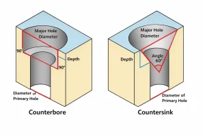
これに対して カウンターボア は、円筒形(平底)の拡大として現れる。平らな底と垂直な側壁が特徴。主に、ソケット・ヘッド・キャップ・スクリューや、底が平らなヘッドを持つ他のファスナーを収容するために使用される。ベアリング面が平らなため、ザグリ穴はより高い締め付け圧力に耐えることができる。
エンジニアリングにおけるその他の穴
穴加工は機械加工の一分野であり、さら穴加工はその一部に過ぎない:
一般的な穴の種類の概要
- ブラインドホール:深さコントロールが重要。
- スルーホール:接続または排水/換気のために材料を完全に貫通する。
- スポットフェイス:穴の周りの粗い面だけを取り除き、ワッシャーのための平らなベアリング面を提供する。
- タップ穴:ボルトをねじ込んで直接固定するための内ネジを採用。
よくあるご質問
皿穴が必要な2つの理由とは?
第一に、安全性と平坦性のため、引っかかりや干渉、傷を防ぐために表面の突起をなくすこと、第二に、空気抵抗低減のため、流線型の表面を維持することである。
よくあるカウンターシンキングの施工ミスとは?
最も一般的なエラーは、カウンターシンクとねじの角度の不一致(例:90°と82°)、深すぎる穴あけ、過度の回転速度による表面のびびりなどである。
皿穴の欠点は何ですか?
カウンターシンクは、穴の開口部で材料の厚みを弱くする。薄板の場合、構造強度が不十分になったり、高い張力でねじ頭が材料を「貫通」したりする可能性がある。
エンジニアリングのカウンターシンクの穴はどのように修理するのですか?
カウンターシンクの加工が大きすぎる場合、一般的な解決策としては、より大きなねじサイズを使用して再度穴をあける、ねじ山補修専用インサート(ヘリコイルなど)を使用する、充填して再加工するなどがある。
結論
皿穴は、工業的な美観と機械的な機能のバランスをとる重要な設計要素です。標準化された寸法選択と精密な切削工程を利用することで、組立精度と製品の耐久性を大幅に向上させることができます。
実際の部品や材料に基づいてカウンターシンクの設計を最適化したい場合は、以下をご利用ください。 図面をアップロードする と重要なパラメータを提供します。当社のエンジニアは、サイズ選択と加工ソリューションの評価をお手伝いします。