
In the field of mechanical manufacturing, holes are among the most fundamental geometric features that constitute a part. From a functional perspective, holes serve not only as the basis for threaded connections but are also widely applied in scenarios such as positioning, weight reduction, guiding, and fluid transmission. While our previous discussions focused on the nuances of thread machining, understanding the macrostructure of holes—namely, the definitions and various types of holes—is a prerequisite for effective process planning and technical drawing annotation. This article will categorize and summarize the common types of holes in machining, analyzing their respective geometric characteristics and application scenarios.
What are Hole Features in Machining?
In an engineering context, hole features refer to more than just cylindrical cavities drilled into a workpiece; they are geometric entities essential for realizing assembly, positioning, and functional logic. A complete hole feature is a complex element defined by multiple design dimensions, typically encompassing the following three core layers:
- Geometric Morphology: This includes the cross-sectional shape of the hole (such as circular or slotted) and its longitudinal profile structure (such as flat-bottomed, tapered, or stepped).
- Spatial Attributes: These define the boundary conditions of the hole—specifically, whether the feature is a “through hole” that completely penetrates the material or a “blind hole” with a specific depth.
- Process and Tolerance: This layer involves requirements for diameter precision, positional accuracy, coaxiality, and surface finish. These attributes directly dictate the selection of subsequent machining operations, such as drilling, reaming, or boring.
Functionally, hole features serve as the physical interfaces for mechanical assembly. They are responsible for accommodating bolts and pins to establish connections, acting as mounting seats for precision bearings, or even performing specific tasks like pressure relief, fluid diversion, or weight reduction. Understanding the multi-dimensional attributes of hole features is the fundamental prerequisite for accurate process planning and technical annotation.
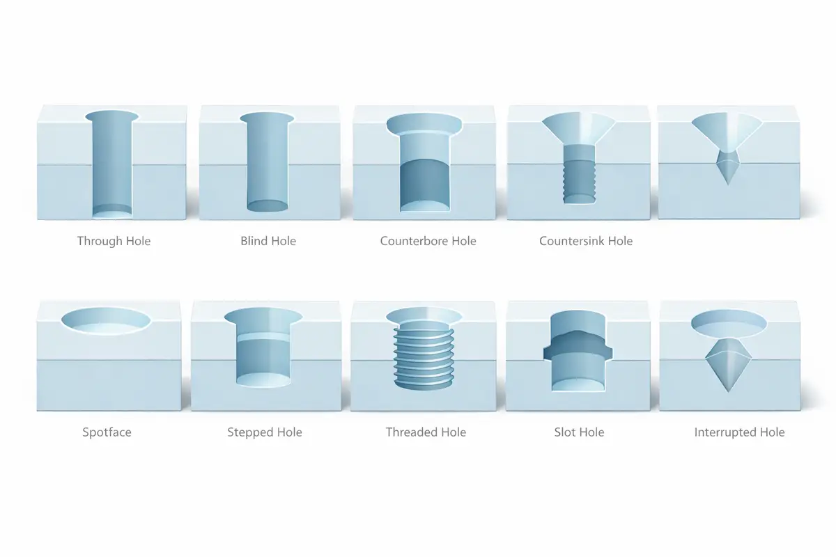
Common Hole Types in Machining
| Hole Type | Shape Characteristics | Core Purpose |
| Through Hole | Penetrates the entire thickness, open at both ends. | Providing clearance for fasteners, shafts, or fluid paths. |
| Blind Hole | Specific depth with a closed bottom. | Used for internal threading, locating pins, or weight reduction. |
| Counterbore | Stepped cylindrical hole with a flat bottom. | Recessing socket head cap screws (SHCS) to prevent interference. |
| Countersink | Conical enlargement at the entrance (typically 90°). | Accommodating flat-head screws for a flush surface finish. |
| Spotface | Very shallow, large-diameter flat surface. | Providing a level seating surface for nuts/washers on rough parts. |
| Stepped Hole | Multiple coaxial diameters arranged in sequence. | Mounting bearings, seals, or providing multi-stage positioning. |
| Tapped Hole | Internal walls featuring a helical thread profile. | Enabling mechanical fastening with bolts or studs. |
| Slotted Hole | Elongated shape with circular ends and straight sides. | Providing adjustment margin for alignment or sliding functions. |
| Interrupted Hole | Non-continuous path broken by cavities or grooves. | Creating crossing oil galleries or passages in complex housings. |
| Center Hole | Small technical hole with a standard 60° taper. | Serving as a datum for centering and support during shaft turning. |
1. Through Hole
A through hole fully penetrates the workpiece, leaving both ends open. In engineering drawings, it is typically defined by the diameter symbol φ (e.g., φ 10 mm). Since it spans the entire thickness, no depth symbol is required. It is the most fundamental and efficient hole type to machine.
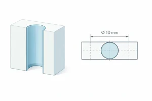
These holes are primarily used for bolt clearance or as channels for shafts. The diameter is usually designed slightly larger than the fastener to provide clearance, which helps absorb manufacturing tolerances and prevents assembly interference.
2. Blind Hole
A blind hole opens on one side but does not penetrate the opposite face. The drawing must specify both the diameter symbol φ and the depth symbol ↓ (e.g., φ 10 ↓ 15). While the bottom typically retains a conical drill point, it can be machined flat if required for specific assemblies.
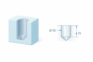
Blind holes are used when only one-sided access is available or to maintain sealing on the opposite side. Designers must monitor the depth-to-diameter ratio, as excessively deep holes complicate chip evacuation and increase the risk of tool breakage.
3. Counterbore
A counterbore is a coaxial, larger-diameter cylindrical step at the hole entrance with a flat bottom. It is identified by the symbol ⌴, which defines both the diameter and depth of the recessed section.
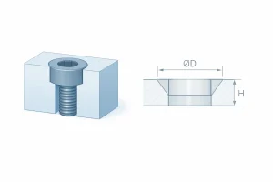
Its primary purpose is to house socket head cap screws, ensuring the head remains flush with or below the surface. The flat bearing surface provides a stable seat, allowing for uniform distribution of the fastener’s preload force.
4. Countersink
A countersink features a conical enlargement at the hole entrance. The drawing uses the symbol ∨ to specify the diameter and the included angle (usually 90°). This creates a circular conical bearing surface for the fastener.
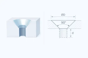
This type allows countersunk screws to sit flush with the material surface, providing a smooth finish for sheet metal or casings. The conical shape also offers a self-centering effect, helping align parts accurately during tightening.
5. Spotface
A spotface is a shallow, flat-bottomed landing machined onto rough surfaces like castings. It is marked with the symbol ⌴ and the letters SF. The depth is minimal, just enough to create a seat slightly larger than the fastener head.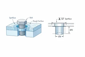
The goal is to provide a smooth bearing surface perpendicular to the hole axis, preventing uneven loading on irregular surfaces. This ensures stability for brackets and housings without requiring the entire surface to be precision-machined.
6. Stepped Hole
A stepped hole consists of multiple coaxial cylindrical segments of varying diameters. It is documented using multiple diameter φ and depth ↓ symbols to define the dimensions of each stage.
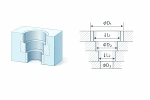
These holes are used to integrate components like bearings, seals, or retaining rings within a single axis. Each step provides a specific shoulder for axial positioning or mechanical stops, common in precision housings.
7. Tapped Hole
A tapped hole has internal helical threads for engagement with a screw or bolt. It is designated by the prefix M (e.g., M8). If it is a blind hole, the effective thread depth is specified with the symbol
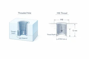
As the most common detachable connection, it is ideal for parts requiring frequent disassembly. In softer materials, thread inserts or increased engagement length are often used to prevent stripping under load.
8. Slotted Hole
A slotted hole is an elongated opening with semi-circular ends. Drawings specify the width and total length to define the range of movement.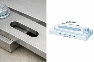
Slots provide a degree of freedom for sliding or adjustment during assembly. They are frequently used for belt tensioning or mounting rails, allowing installers to compensate for manufacturing tolerances or thermal expansion.
9. Interrupted Hole
An interrupted hole is one where the internal wall is cut by other features, such as internal cavities or crossing oil galleries. This results in a non-continuous internal circumference.
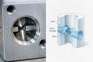
Common in hydraulic manifolds, these holes allow for high-density internal routing. However, they increase the difficulty of deburring and cleaning. Design focus must be placed on controlling burrs at the intersections to ensure proper fluid flow.
10. Center Hole
A center hole is a process hole at the end of a shaft, featuring a standard 60° conical seat. It is indicated by a specific process symbol to facilitate the use of lathe centers.
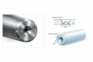
Center holes serve as the primary datum for machining and inspection. By mounting the part between centers, high coaxiality and straightness are maintained, which is critical for the smooth operation of rotating shafts.
How to Choose the Right Hole Type?
In engineering design, selecting the appropriate hole type is not a random decision but a balanced trade-off between functional requirements, manufacturability, and overall cost. A well-designed hole feature ensures assembly precision while significantly reducing manufacturing complexity.
Key factors to consider when selecting a hole type include:
-
Functional & Assembly Requirements: This is the primary criterion for selection. If the goal is a flush surface, choose a Counterbore (⊔) or Countersink (∨) based on the fastener head shape. If the part requires positional adjustment during installation, a Slotted Hole is necessary. For drive components involving precise axial positioning, Stepped Holes are the optimal choice for multi-stage support.
-
Material & Surface Condition: The material and initial surface state of the workpiece limit hole options. For instance, when installing bolts on rough cast or forged surfaces, a Spotface (SF) must be designed to provide a perpendicular bearing surface, preventing bolt failure due to eccentric loading. For soft metals like aluminum, designing Threaded Holes (M) often requires increased effective depth or space for thread inserts.
-
Manufacturing & Economics: Follow the “simple-to-complex” principle. Through Holes (Ø) have the lowest cost and easiest chip evacuation, making them the preferred choice. In contrast, Blind Holes (↓), especially deep ones, significantly increase tool wear and cleaning difficulty. Additionally, unifying hole diameters across a part reduces tool changes in CNC machining, which is key to lowering unit costs.
-
Process Benchmarking: For shaft-like parts requiring multiple setups or high-precision grinding, a Center Hole must be pre-designed. It serves not only as a rotational support during machining but also as a consistent datum for measurement and alignment throughout the production cycle, ensuring the coaxiality of the finished product.
Conclusion
Precise definition of hole features is essential for balancing part functionality, assembly accuracy, and manufacturing efficiency. Whether employing basic through holes or complex engineering features like counterbores, selecting the appropriate type optimizes process paths and reduces production costs.
If you are looking for the optimal hole-making solution for a specific project or require customized technical advice, our engineering team is ready to assist. Contact us today for expert consultation and detailed quotes.