
La fabrication CNC de composants d'arbres de précision exige non seulement des profils dimensionnels stricts, mais repose aussi fortement sur l'intégration de séquences logiques et le contrôle de la déformation. Chaque étape de la production, de l'ébauche initiale à la rectification cylindrique de précision finale, a un impact direct sur le taux de rendement global. Cet article fournit une vue d'ensemble analytique du flux de production de base pour les pièces d'arbres, examine systématiquement les caractéristiques d'application des matériaux d'arbres courants et discute des goulets d'étranglement typiques rencontrés dans l'atelier.
Qu'est-ce que l'usinage des arbres ?
L'usinage d'arbres désigne le processus de transformation de barres de métal ou de plastique en pièces en forme d'arbre aux dimensions, formes et qualités de surface spécifiques, grâce à une série d'opérations d'usinage mécanique.
Comme les composants des arbres tournent généralement à des vitesses élevées et subissent des charges alternées pendant leur fonctionnement, l'usinage des arbres répond à des exigences strictes en matière de précision dimensionnelle (les tolérances des tourillons doivent généralement être contrôlées au niveau du micron), de tolérances géométriques (telles que la coaxialité, la cylindricité et la rondeur) et de rugosité de surface. L'application de la commande numérique par ordinateur (CNC) permet de produire en série, de manière efficace et automatique, des composants d'arbres précis et très complexes.
Types courants de composants d'arbres
En fonction des caractéristiques structurelles et des scénarios d'application, les composants d'arbres couramment trouvés dans les secteurs industriels comprennent les types suivants :
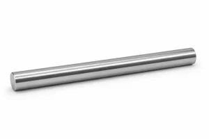
Arbres droits
Arbres dont le diamètre est uniforme sur toute la longueur. Ils présentent la structure la plus simple et sont couramment utilisés pour le guidage général, le glissement ou la transmission directe de puissance.
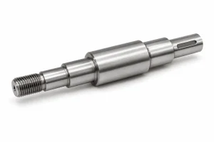
Arbres étagés
Arbres distribués avec plusieurs sections de diamètres différents. Cette conception est la plus répandue, facilitant l'installation de roulements, d'engrenages ou de poulies, et utilisant les faces de marche pour le positionnement axial.
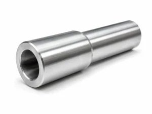
Arbres creux
Arbres dotés d'un trou central traversant. Ils sont essentiels pour réduire le poids de la structure, acheminer d'autres composants (tels que les conduites hydrauliques ou le câblage) ou servir d'arbres de manchon.
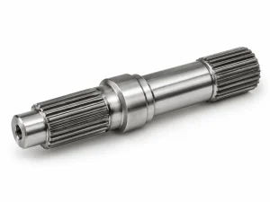
Arbres cannelés
Arbres dont les fentes d'entraînement longitudinales à plusieurs dents sont usinées sur le diamètre extérieur. Ils sont utilisés pour la transmission de couples élevés et l'alignement axial de haute précision, que l'on trouve couramment dans les boîtes de vitesses automobiles et les machines lourdes.
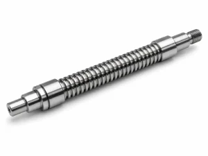
Vis
Arbres conçus avec des filets de transmission continus (tels que des filets trapézoïdaux ou des rainures de vis à billes). Ils sont utilisés pour convertir un mouvement rotatif en un mouvement linéaire de haute précision, fréquemment observé dans les systèmes d'alimentation des machines-outils à commande numérique.
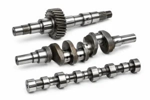
Arbres de transmission, vilebrequins et arbres à cames (arbres spécialisés)
Arbres spécialisés qui intègrent des caractéristiques d'engrenage ou des structures excentriques pour réaliser des conversions complexes d'énergie et de mouvement. Il s'agit de pièces de précision présentant des exigences de traitement élevées et des configurations complexes.
Procédés d'usinage primaire pour les composants d'arbres
L'usinage des composants d'arbres est rarement réalisé en une seule opération ; il nécessite au contraire une chaîne de processus multi-processus, collaboratifs et échelonnés.
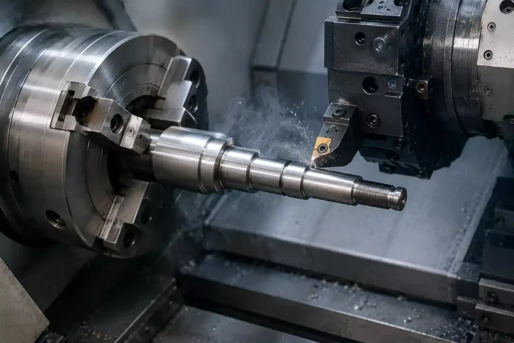
Tournage CNC
Tournage est la méthode d'usinage la plus fondamentale pour les composants d'arbres. La barre tourne à grande vitesse dans la broche tandis que l'outil de coupe se déplace le long de la ligne axiale pour couper le diamètre extérieur.
- Tournage brutal: Enlève rapidement la plus grande partie de l'excédent de matière du flan.
- Finir le tournage: Garantit les dimensions du diamètre extérieur et la rugosité de la surface, jetant les bases d'un meulage ultérieur ou d'un assemblage direct.
- Tourner-fraiser Tourner-center: Les machines multitâches modernes de tournage-fraisage à commande numérique peuvent effectuer le tournage du diamètre extérieur et le fraisage de caractéristiques complexes en un seul réglage, éliminant ainsi les erreurs de positionnement causées par le serrage secondaire.
Fraisage, perçage et taraudage
Au-delà du diamètre extérieur, les arbres doivent souvent être reliés à d'autres composants, ce qui nécessite des opérations d'usinage auxiliaires :
- Fraisage: Principalement utilisé pour usiner des rainures de clavettes, des cannelures, des plats ou des surfaces planes spécifiques sur l'arbre.
- Perçage et taraudage: Il s'agit de percer des trous centraux sur les faces d'extrémité de l'arbre (ce qui est essentiel pour l'alignement de l'usinage) ou de traiter les trous filetés et les passages d'huile internes le long du corps et des extrémités de l'arbre.
Meulage et traitement thermique
Pour les arbres dont les exigences en matière d'accouplement sont très précises (comme les zones de tourillons où sont installés les roulements), le tournage seul ne suffit souvent pas :
- Traitement thermique: Après l'usinage brut ou semi-fini, les arbres subissent généralement un traitement thermique tel que la trempe et le revenu (pour améliorer la résistance mécanique globale) ou la trempe par induction (pour augmenter la dureté de la surface et la résistance à l'usure).
- Broyage: Les arbres subissent de légères déformations après le traitement thermique. L'utilisation d'une rectifieuse cylindrique pour la rectification de finition est une étape essentielle pour obtenir une grande précision dimensionnelle (grade IT6 ou supérieur) et une rugosité de surface idéale (Ra 0,8∼0,2 μm).
Traitement de surface
Pour améliorer la résistance à la corrosion, la résistance à l'usure ou l'esthétique de l'arbre, des traitements de surface sont généralement effectués après l'usinage :
- Oxyde noir / Oxydation: Fournit des capacités fondamentales de prévention de la rouille.
- Placage électrolytique: Le chromage dur, qui améliore considérablement la dureté et la résistance à l'usure de la surface de l'arbre, est couramment appliqué aux tiges de piston hydrauliques.
- Sablage / Polissage: Optimise l'aspect cosmétique ou réduit davantage le coefficient de frottement de la surface.
Matériaux courants pour l'usinage des arbres
Lors de la conception et de la fabrication de composants d'arbres, le choix des matériaux est primordial. Il détermine directement la capacité de charge, la résistance à la fatigue et la durée de vie, tout en influençant fortement l'usinabilité et l'efficacité du traitement thermique. Les concepteurs doivent trouver un équilibre entre les propriétés physiques du matériau et les coûts de fabrication en fonction des conditions d'exploitation telles que la vitesse, la charge, les chocs et les environnements corrosifs.
- Acier de construction à teneur moyenne en carbone: En tant que matériau d'arbre traditionnel le plus largement utilisé, il offre un faible coût et une excellente usinabilité. Après trempe et revenu ou durcissement superficiel, il présente de bonnes propriétés mécaniques globales, ce qui le rend idéal pour les arbres de transmission ordinaires et les arbres droits soumis à des charges modérées et à des vitesses standard.
- Acier de construction allié: Ce matériau, enrichi d'éléments d'alliage tels que le chrome et le molybdène, présente une résistance et une ténacité extrêmement élevées, ainsi qu'une trempabilité supérieure. Il peut supporter des couples et des charges d'impact plus importants après traitement thermique, et est couramment utilisé pour les arbres d'entraînement principaux soumis à des exigences strictes en matière de vitesse, de charges lourdes et d'anti-fatigue.
- Acier à roulements et acier à ressorts: Cette catégorie atteint une dureté exceptionnellement élevée après traitement thermique (généralement jusqu'à HRC60 ou plus), avec une superbe résistance à l'usure et une grande résistance à la fatigue de contact. Elle est principalement utilisée pour les composants de transmission de haute précision, tels que les broches de machines-outils de précision, les vis à billes et les sections de tourillons en contact direct avec les éléments roulants des roulements.
- Acier inoxydable: Connues pour leur excellente résistance à l'oxydation et à la corrosion, les nuances d'usinage libre sont couramment utilisées pour les arbres antirouille standard ; les nuances résistantes à la corrosion sont adaptées aux environnements chimiques, médicaux et marins ; tandis que les nuances martensitiques à haute teneur en carbone offrent une dureté et une résistance à l'usure élevées après traitement thermique pour les arbres de vannes spécialisés.
- Alliages légers et non ferreux: Alliages d'aluminium Les alliages de cuivre offrent un faible poids, une dissipation rapide de la chaleur et une bonne résistance à la corrosion pour l'aérospatiale ou les structures légères et sensibles au poids. Les alliages de cuivre offrent de bonnes propriétés autolubrifiantes et une bonne résistance à l'usure. Ils sont régulièrement utilisés pour les arbres de moteurs miniatures, les arbres d'instruments ou les arbres rotatifs qui s'accouplent avec des bagues.
Défis courants dans l'usinage des arbres
Dans l'atelier de production CNC proprement dit, l'usinage de composants d'arbres se heurte souvent à de nombreux défis physiques et technologiques. Voici quelques-unes des difficultés de fabrication les plus courantes :
1. Déformation des arbres élancés
Lorsque le rapport longueur/diamètre d'un arbre est relativement important (on parle généralement d'arbre élancé lorsque L/D>12), la rigidité structurelle de la pièce à usiner diminue considérablement. Pendant le processus de tournage, sous l'action combinée des forces de coupe, du poids de la pièce et des forces centrifuges dues à la rotation à grande vitesse, les arbres minces sont très sensibles à la flexion et aux vibrations. Il en résulte non seulement une erreur dimensionnelle en forme de "selle", où la pièce est épaisse au milieu et mince aux deux extrémités, mais aussi des marques de frottement distinctes sur la surface de l'arbre, ce qui dégrade gravement la qualité de la pièce. rugosité de la surface.
2. Distorsion due au traitement thermique
Les composants d'arbres soumis à des charges élevées nécessitent généralement des processus de traitement thermique tels que la trempe et le revenu ou la trempe superficielle par induction. Cependant, le réchauffement et le refroidissement rapides au cours du traitement thermique génèrent d'importantes contraintes internes dans l'arbre, entraînant une déformation par flexion ou par torsion le long de la ligne axiale. La correction de ces déformations lors des opérations de rectification de précision ultérieures, tout en évitant les déformations secondaires provoquées par la chaleur de coupe pendant l'usinage, constitue une difficulté majeure dans le contrôle des tolérances géométriques.
3. Contrôle de la coaxialité
Les arbres étagés comprennent généralement plusieurs segments d'arbres de diamètres différents utilisés pour monter des roulements, des engrenages ou des accouplements. Ces surfaces d'accouplement critiques sont souvent soumises à des exigences extrêmement rigoureuses en matière de coaxialité, de battement radial et de cylindricité. Si le point de référence de positionnement se déplace légèrement au cours de l'usinage en raison de multiples retournements de pièces ou d'un serrage répétitif, ou si la précision de la liaison multi-axes de la machine-outil elle-même est insuffisante, il peut facilement en résulter un désalignement des axes des différents segments de l'arbre, ce qui se traduit par des produits finis dépassant les limites de faux-rond.
4. Évacuation et refroidissement des puces à trous profonds
Pour les arbres creux ou les composants d'arbres présentant de longs alésages de transmission internes, l'usinage de trous profonds représente un goulot d'étranglement essentiel. En raison de la grande profondeur du trou, une fois que l'outil de coupe pénètre à l'intérieur, la chaleur de coupe est exceptionnellement difficile à dissiper et les copeaux ont tendance à s'accumuler au fond du trou sans être évacués en douceur. Cela entraîne facilement une surchauffe, une usure ou une rupture de l'outil et peut facilement marquer la surface usinée de l'alésage interne, ce qui rend difficile la garantie de la précision dimensionnelle et de la rectitude du trou intérieur.
5. Indexation et positionnement Alignement
Les rainures de clavettes ou les cannelures sur les arbres exigent généralement une très grande précision en ce qui concerne leur symétrie ou leur positionnement angulaire par rapport à l'axe de l'arbre. Lors du fraisage de ces éléments, des erreurs d'indexation se produisent si la tête d'indexation ou le centrage du quatrième axe est imprécis, ou si la pièce subit un glissement de rotation minime. Il en résulte des rainures de clavettes excentrées ou un pas de dents cannelées inégal, ce qui finit par avoir un impact sur l'assemblage final avec les engrenages et les accouplements.
Conclusion
La qualité de l'usinage CNC des arbres dépend de la planification de l'ensemble du processus de fabrication. Pour relever des défis tels que la déformation, les contraintes thermiques et le faux-rond, il faut moins de machines que d'équipements pratiques et d'expérience en atelier. Il est essentiel d'équilibrer l'acheminement du processus et les paramètres de coupe pour obtenir une production de masse de haute précision et rentable.
Voici la version anglaise concise et non absolue qui correspond parfaitement au ton de votre texte chinois :
FAQ
Qu'est-ce que l'usinage des arbres ?
Il s'agit généralement du processus de fabrication de composants en forme d'arbre à partir de barres de métal ou de plastique par des opérations telles que le tournage, le fraisage, le meulage et le traitement thermique. Ces pièces sont principalement utilisées pour transmettre un couple, soutenir des éléments rotatifs ou maintenir l'alignement dans des assemblages mécaniques.
Quel est le procédé d'usinage utilisé pour fabriquer les arbres ?
En raison de leur symétrie de rotation, la plupart des arbres sont généralement produits en utilisant le tournage CNC comme méthode principale. En fonction de la conception, des opérations ultérieures telles que le fraisage, le perçage, la rectification de précision ou la finition de surface sont souvent intégrées pour produire des clavettes, des filetages, des sièges de roulements ou pour répondre à des exigences spécifiques en matière de tolérance.
Quels sont les matériaux couramment utilisés pour l'usinage des arbres ?
La sélection comprend généralement de l'acier à moyenne teneur en carbone, de l'acier allié, de l'acier inoxydable, des alliages d'aluminium et des alliages de cuivre. Les aciers au carbone et les aciers alliés sont fréquemment utilisés pour leur solidité et leur résistance à la fatigue, l'acier inoxydable est souvent choisi pour les environnements sujets à la corrosion, tandis que l'aluminium et les alliages de cuivre sont généralement utilisés dans des applications légères ou spécialisées.