
In engineering drawings, quotations, and daily machining communication, the terms “tapped hole” and “threaded hole” are very often used as if they mean the same thing. For aluminum parts, standard thread sizes, and high-volume production, this wording rarely causes real problems, and tapping is usually assumed as the default process.
However, once materials shift to stainless steel, titanium, or high-strength alloys, or when the design involves deep blind holes, precision assemblies, or high-value custom parts, the choice of thread-forming method becomes critical. Tool breakage risk, scrap rate, cycle time, and overall part cost are all directly affected by whether tapping or another threading method is used.
For this reason, the real question is not only “what is the difference between the two terms,” but how tapped holes and threaded holes truly differ in process behavior, size control, connection design, and practical machining selection.
Tapped Hole
Before selecting a tapping method for CNC production, it is essential to first understand what a tapped hole truly represents in manufacturing terms.
What Is a Tapped Hole?
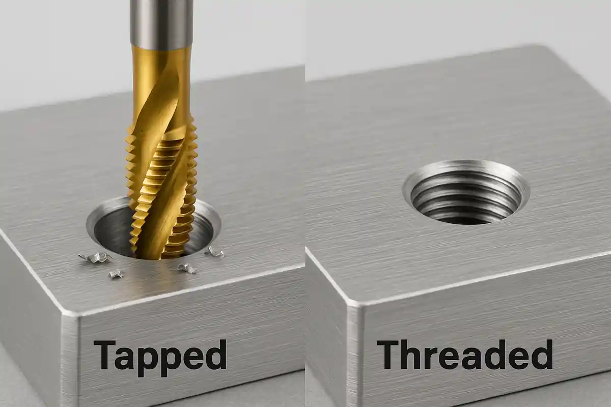
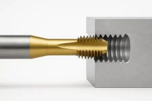
A tapped hole is created by cutting or forming internal threads directly inside a pre-drilled hole using a tap. During this process, the tap removes material or plastically deforms it to generate the thread profile in a single operation. From a manufacturing standpoint, a tapped hole describes a specific machining action rather than the final structural result. In terms of function, the finished feature is still a standard internal thread capable of mating with a screw or bolt.
Tools Used for Tapping
Tapping relies on taps as the primary cutting tool, including machine taps, hand taps, and form (roll) taps. The operation also requires a properly sized drill to produce the tap hole, as well as a chamfer tool to prepare the entry. On CNC machines, rigid tapping systems or dedicated tapping holders are typically used to synchronize spindle rotation and feed.
Advantages of Tapped Holes
- Very fast cycle time for each hole
- Highly suitable for automated, high-volume production
- Low tool cost compared with other threading methods
- Mature and widely standardized process
- Excellent compatibility with common metric thread sizes
Limitations and Risks of Tapped Holes
- Highly sensitive to material hardness (high breakage risk in stainless steel and titanium)
- Poor chip evacuation in deep blind holes
- Tap breakage often results in complete part scrap
- Thread size cannot be fine-tuned after cutting
- Tool wear increases rapidly in difficult-to-machine materials
Tap Hole Size vs Nominal Thread Size
A critical but often misunderstood issue is that the tap hole diameter is not equal to the nominal thread size. The correct tap drill size must be selected before threading. For example, an M6 thread does not use a 6 mm drill for the tap hole; it typically requires a drill around 5 mm.
If the tap hole is too large, thread engagement will be insufficient, leading to reduced strength and stripping risk. If it is too small, cutting forces increase dramatically, accelerating tool wear and greatly raising the chance of tap breakage. Therefore, correct tap hole sizing directly determines both thread integrity and scrap risk.
Threaded Hole
From a manufacturing standpoint, once the concept of a threaded hole is clearly defined, the next step is to understand the different methods engineers use to create it in practice.
What Is a Threaded Hole?
A threaded hole is not a machining method but a description of the final geometric result. Any hole that contains a standard internal helical thread capable of mating with a fastener can be defined as a threaded hole. Whether the thread is produced by tapping, thread milling, single-point internal turning, or by installing a thread insert, the outcome is still a threaded hole. In this sense, the term describes the result, not the process.
Tools and Methods Used to Create Threaded Holes
Threaded holes can be produced using taps, thread mills on CNC machining centers, internal threading tools on lathes, or thread inserts such as Helicoil and Keensert. Each method offers different advantages in terms of flexibility, strength, and control.
Advantages of Threaded Holes
- Flexible manufacturing methods (milling, turning, inserts)
- Much better stability in deep holes and hard materials
- CNC compensation allows fine adjustment of thread fit
- Lower catastrophic scrap risk for high-value parts
- Better long-term reliability in precision and safety-critical assemblies
Disadvantages of Threaded Holes
- Higher tooling and programming cost
- Longer machining time per hole
- Greater dependence on machine rigidity and operator experience
- Less economical for very high-volume, cost-sensitive products
Threaded Hole Symbols and Drawing Callouts
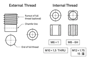
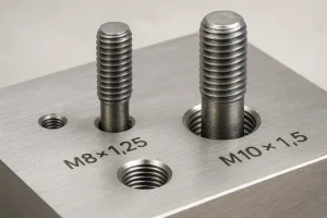
On engineering drawings, threaded holes are identified using standard callouts such as “M6 × 1” or “M8 – 6H.” The letter “M” indicates a metric thread, the number defines the nominal diameter, the second number represents the pitch, and the tolerance class defines thread accuracy. Additional notes such as “THRU” or depth values are commonly used for through or blind holes. It is important to note that these symbols define the thread geometry and tolerance, not the specific machining method.
Key Differences Between Tapped Holes and Threaded Holes
With both tapped holes and threaded holes clearly defined, the real engineering differences between these two concepts can now be evaluated more systematically.
Difference in Concept Level
A tapped hole refers to a specific manufacturing process, while a threaded hole refers to the final threaded structure. A tapped hole is one way to create a threaded hole, but a threaded hole does not necessarily originate from tapping.
Difference in Machining Path
Tapping forms the thread in one continuous operation. Threaded holes, on the other hand, can be produced through multiple methods such as thread milling or internal turning, which offer more gradual material removal.
Difference in Material Adaptability
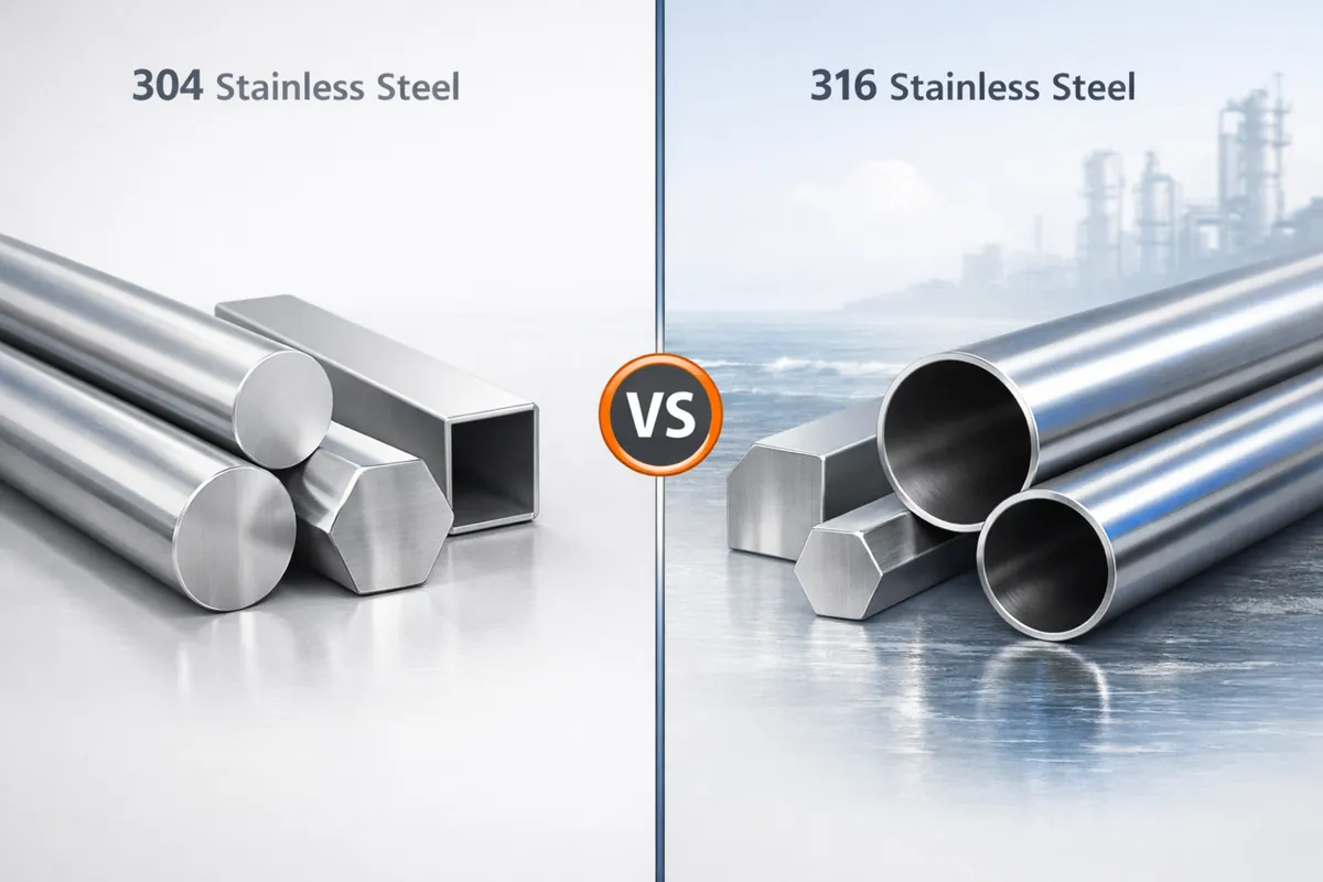
Tapping performs extremely well in aluminum, brass, and mild steel but becomes risky in stainless steel, titanium, and high-temperature alloys. Thread milling and turning are far more adaptable to these difficult materials.
Difference in Deep-Hole Risk
For shallow holes, both methods are relatively stable. In deep blind holes, chip congestion during tapping raises the probability of tool breakage sharply, while thread milling maintains significantly better stability.
Difference in Precision Adjustment
Tapped threads are essentially fixed once cut, whereas thread-milled holes allow CNC compensation for fine size adjustment.
Difference in Cost and Scrap Risk
Tapping offers the lowest per-hole manufacturing cost but carries a higher catastrophic scrap risk in difficult conditions. Thread milling has higher per-hole cost but significantly reduces the probability of total part loss.
Differences in Connection Design Using Threaded Holes and Self-Tapping Holes
In real assemblies, internal threads are used in several typical connection configurations. Each connection type differs significantly in load capacity, assembly life, material compatibility, and long-term reliability. As a result, they also place very different demands on the machining process and structural design.
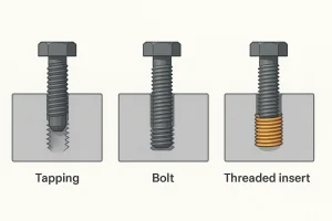
Direct Internal Thread in the Base Material
This is the most common and lowest-cost connection method, typically used in low-load, lightweight, and cost-sensitive designs. Internal threads are formed directly in the base material, such as aluminum, low-carbon steel, or brass, without introducing additional components. The structure is simple, assembly efficiency is high, and manufacturing cost is minimal.
However, the wear resistance of the base material threads is limited. Under frequent assembly and disassembly, the risk of thread stripping increases, and the connection strength depends heavily on the strength of the base material itself. This method is therefore not suitable for high-load or high-reliability applications.
Standard Threaded Hole with Bolt Connection
This is by far the most widely used connection method in mechanical structures and covers the majority of general industrial applications. It is suitable for both through holes and blind holes and can be combined with fasteners of different strength grades.
This type of connection offers stable strength, broad applicability, and proven long-term reliability. It is commonly used in machine frames, support structures, transmission components, and standard industrial assemblies, making it the default choice in most engineering designs.
Threaded Hole with Thread Inserts
When the base material is soft, the assembly frequency is high, or the load level is significant, relying solely on the base material threads often fails to meet long-term reliability requirements. In such cases, thread inserts such as Helicoil or Keensert are installed inside the threaded hole to reinforce the connection.
This solution is particularly suitable for aluminum alloys, magnesium alloys, high-cycle assembly environments, and high-load or safety-critical structures. Thread inserts significantly improve wear resistance, tensile strength, and long-term stability. At the same time, they also impose higher requirements on hole accuracy, coaxiality, and installation process control.
When to Use Tapping and When to Use Other Threading Methods
In real engineering practice, the selection of a threading method is not based on whether a thread can be produced, but on whether a specific process truly matches the material properties, hole geometry, tolerance requirements, production volume, and overall part value. Different threading methods serve different manufacturing objectives—some prioritize efficiency and cost, while others emphasize safety, stability, and long-term reliability.
When to Prefer Tapped Holes
When the workpiece is made from easy-to-machine materials such as aluminum alloys, brass, or low-carbon steels, tapping remains the most efficient and cost-effective internal threading method. Under conditions where hole depth is moderate and chip evacuation is favorable, tapping is typically highly stable, with low tool wear and a low risk of tap breakage.
In medium to high-volume automated CNC production, tapping provides clear advantages in cycle time and unit cost. For this reason, it is still widely used as the default solution for standard brackets, electronic enclosures, sheet metal parts, aluminum structural components, and general industrial fastening features.
Typical conditions where tapped holes are preferred include:
-
Soft and easy-to-machine materials such as aluminum, brass, and low-carbon steel
-
Moderate hole depth, usually not classified as deep blind holes
-
Favorable chip evacuation and simple hole structures
-
Medium to high production volumes with strong sensitivity to cycle time and unit cost
When to Prefer Threaded Holes (Thread Milling, Turning, or Inserts)
Once the material shifts to stainless steel, titanium, heat-treated steels, or high-temperature alloys, the risk associated with tapping increases significantly. This is especially true for deep blind holes, small-diameter deep holes, or structures with restricted chip evacuation, where the probability of tap breakage rises sharply. When a tap breaks in these situations, part recovery is often impossible, resulting in total scrap.
Under these conditions, thread milling and single-point internal threading offer much higher process controllability. Because material removal is performed gradually and CNC compensation can be applied to fine-tune thread size, the consistency and reliability of the threads are greatly improved. In applications involving soft base materials or repeated assembly, threaded inserts can further enhance wear resistance and joint strength.
Typical conditions where threaded holes should be preferred include:
-
Hard or difficult-to-machine materials such as stainless steel, titanium, heat-treated steels, and high-temperature alloys
-
Complex hole geometries such as deep blind holes or small-diameter deep holes
-
High precision and tight assembly tolerance requirements
-
High-value parts where scrap cost is unacceptable
Typical CNC Machining Applications
Typical Applications of CNC Tapping
-
Electronic enclosures and housings
-
Standard brackets and mounting plates
-
Sheet metal parts with threaded features
-
High-volume fastening features in aluminum and mild steel
-
Consumer electronics and general industrial components
Typical Applications of Thread Milling
-
Aerospace structural parts and engine components
-
Medical devices and surgical instruments
-
Precision automation and robotics components
-
Deep blind holes in stainless steel and titanium
-
Complex angular or multi-axis threaded features
With the growing adoption of 5-axis machining, thread milling is becoming increasingly advantageous in space-constrained geometries and complex aerospace-grade structures.
Conclusion
A threaded hole describes a structural result, while tapping is simply the most common way to create it. The true success of thread design and machining selection does not depend on whether a hole has threads, but on the material type, hole depth, breakage risk, cost structure, and long-term reliability. Choosing the right threading method at the design stage is the key to balancing efficiency, quality, and manufacturing risk.
If your project involves stainless steel, titanium, deep blind holes, or high-value precision parts, selecting the right threading method at the design stage can significantly reduce scrap risk and machining cost. Our engineering team can help evaluate the most suitable solution for your application.