
A thread is a fundamental tool used to connect two fasteners. From aerospace vehicles soaring in the sky to oil drilling platforms deep in the ocean, its presence is seen everywhere. It serves as the bedrock of modern industrial assembly, power transmission, and fluid sealing. . So, how exactly are threads machined?
This article discusses the underlying logic of thread machining, its core parameters, and the primary manufacturing methods used in the industry today. By understanding these technical details, you can better optimize your designs and ensure the long-term reliability of mechanical connections.
What is Thread Machining?
Thread machining refers to a precise subtractive manufacturing process responsible for processing a cylindrical or conical workpiece surface into a continuous helical groove with a specific cross-sectional shape. This is accomplished by maintaining strict helical linear synchronization between the tool and the workpiece.
By utilizing methods such as cutting, grinding, or forming, manufacturers produce threads that meet exact engineering specifications. This process is primarily applied in fastener production, precision lead screw systems, and the sealing of high-pressure pipelines. Before determining the optimal machining plan, it is essential to understand the core parameters of threads.
Core Parameters of Threads
As a highly standardized machining process, threading involves several parameters that must be strictly controlled during manufacturing. Mastering these parameters helps in better achieving the design requirements of thread machining and ensures part interchangeability.
Thread Diameter
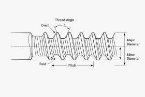
Thread diameter is a composite indicator including the major diameter, pitch diameter, and minor diameter. The major diameter is the nominal size used for identification (e.g., M10), while the pitch diameter is the critical dimension for determining the quality of the thread fit—representing the imaginary diameter where the thread thickness equals the groove width. The minor diameter relates directly to the root strength and the overall tensile capacity of the part.
Pitch
Pitch is the axial distance between corresponding points on adjacent thread forms along the pitch line. It is the most fundamental parameter for CNC programming and tool selection. In the machining cycle, the pitch directly dictates the axial feed rate; any minor deviation can result in cumulative error, preventing proper assembly of long-threaded sections.
Lead
Lead is the axial distance a thread moves when rotated one full turn. For single-start threads, the lead is numerically equal to the pitch. For multi-start threads, however, the lead is calculated by multiplying the pitch by the number of starts. This parameter is critical for transmission systems where a specific linear displacement per revolution is required.
Thread Angle
The thread angle defines the geometric shape of the thread cross-section. Metric standards typically utilize a 60° angle, while British standards (Whitworth) often use 55°. The design of this angle is a careful balance between the ease of material removal during cutting and the final load-bearing strength of the connection, as well as its self-locking capability.
Direction
Direction specifies the orientation in which a thread is tightened, categorized into right-hand and left-hand. Right-hand threads are the global industrial standard for general fastening, following the “clockwise to tighten” rule. Left-hand threads are reserved for specific anti-loosening applications or specialized mechanical linkage scenarios where standard rotation would cause the component to unscrew.
Thread Machining Types
Criteria for thread classification are diverse. Based on the position of the machined surface, thread types are primarily divided into internal and external threads, which require distinct tooling and path strategies.
Internal Threads
An internal thread, also known as a female thread, is a helical structure processed on the inner wall of a hole. It is commonly found in nuts, manifold ports,
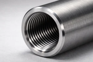
or threaded holes on a machine body. Internal thread machining is utilized whenever a design requires fastening a bolt or screw into a solid component, often involving tapping or internal boring tools.
External Threads
An external thread differs from an internal thread in that the structure is located on the outer surface of a cylinder or cone. It is primarily used for bolts, studs, and transmission shafts.
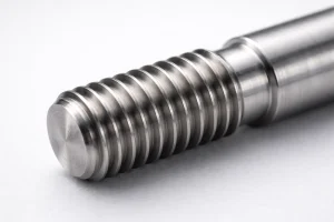
These are mainly processed through turning, die cutting, or rolling, and require precise control of the workpiece’s outer diameter before the threading begins.
How to Machine Threads
There are several methods for machining threads, but they generally follow a standardized sequence to ensure the precision of the helical tool path. The following stages represent the typical workflow for producing a high-quality threaded part.
Preparation Stage
Before the actual threading begins, the workpiece must be processed to the correct pre-machining dimensions. For external threads, this involves turning the shaft to the major diameter. For internal threads, a precise tap drill hole must be bored. A 45° lead-in chamfer at the start is essential to protect the tool tip and facilitate assembly.
Roughing Stage
The goal of the roughing stage is to remove the bulk of the material efficiently and stably. In CNC machining, this is achieved through multiple passes that gradually reach the required depth. Utilizing a “flank infeed” strategy is often recommended to improve chip evacuation and reduce the thermal load on the tool tip, preventing premature wear.
Post-processing Stage
After the main cutting paths are completed, a final finishing pass is performed to correct geometric errors and improve surface finish. The final stage involves a rigorous inspection using thread gauges, such as Go and No-Go gauges, to ensure the pitch diameter and functional fit meet the required design tolerances.
Thread Machining Methods
Selecting the right machining method is crucial for balancing production efficiency and precision. Based on the workpiece geometry and material, four mainstream methods are typically employed.
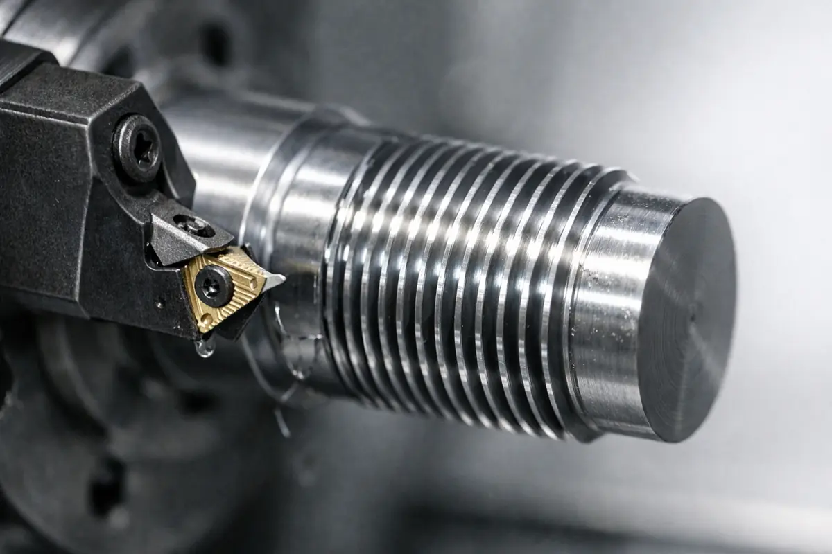
Thread Turning
Thread turning is the most universal method for rotational parts. It uses the electronic synchronization of the CNC lathe spindle and the tool feed to create threads through multiple passes.
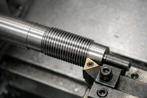
Its core advantage is extreme flexibility, allowing for a wide range of thread specifications and profiles on a single machine.
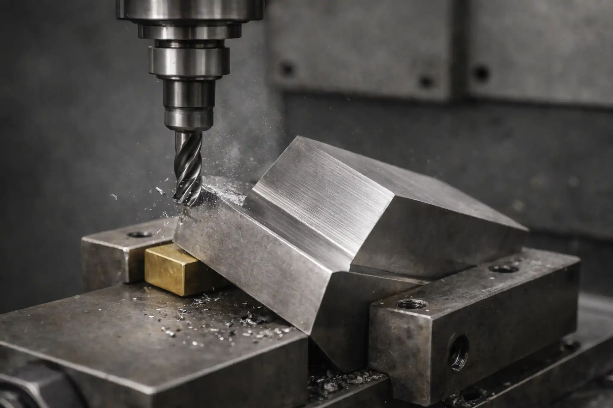
Thread Milling
Thread milling uses a three-axis linkage on a machining center to perform helical interpolation. It is ideal for large, non-symmetrical parts or difficult-to-cut materials like titanium.
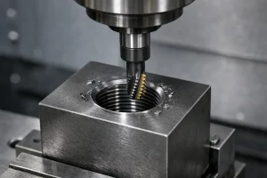
It offers high safety because the tool is smaller than the hole, and it produces superior root quality compared to traditional methods.
Tapping
Tapping is the most efficient way to machine standard internal threads, particularly for holes below M12. This involves using a tap to cut or extrude threads within a pre-drilled hole.
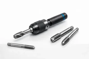
Modern machines use rigid tapping technology to achieve high production speeds, making it the primary choice for mass production.
Die Threading
Die threading primarily uses a die to perform forming cuts on the outer surface of a cylinder.
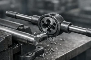
While it lacks the flexibility of CNC turning, it remains a quick and effective method for producing standard fasteners or performing manual repairs and pipe threading in the field.
Thread Design Considerations
Proper design can significantly reduce machining difficulty and extend part life. By optimizing the geometric details of a threaded feature, manufacturers can prevent tool failure and improve assembly performance.
Provide Thread Relief: Always design a relief groove or “undercut” at the end of the thread, especially for external threads meeting a shoulder. This prevents tool collision during the high-speed exit and ensures the mating part can be fully tightened against the shoulder.
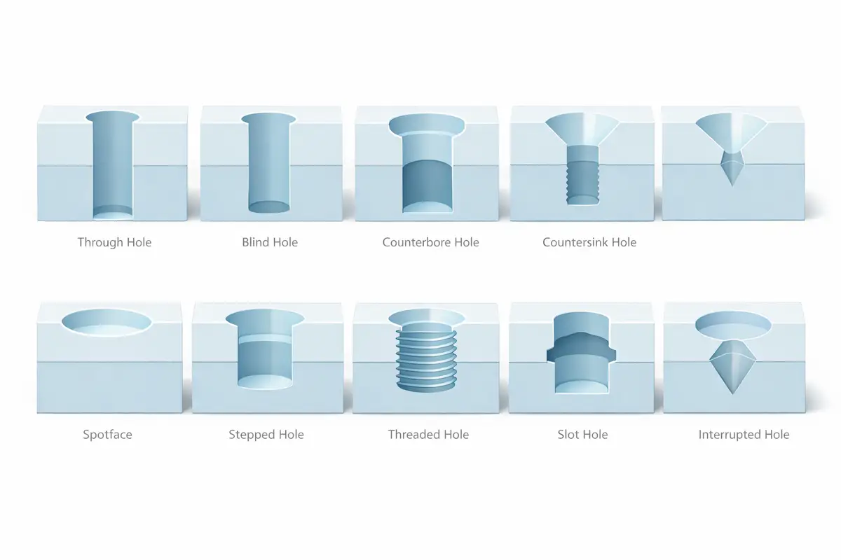
Optimize Blind Hole Depth: For internal threads in blind holes, the total hole depth should exceed the effective thread depth by at least 2 to 3 pitches. This provides a necessary reservoir for chip accumulation, preventing the tap from bottoming out and breaking during the machining process.
Lead-in Chamfers: A 45° chamfer at the start of the thread is essential for high-quality manufacturing. It helps with assembly alignment, protects the first thread from impact damage, and reduces the initial cutting force on the tool tip during the entry pass.
Material and Pitch Matching: Consider reducing the thread height percentage for extremely hard materials to lower cutting forces. For tough alloys, using a coarser pitch can often lead to more stable machining results and reduced tool wear.
Frequently Asked Questions
Is thread milling faster than tapping?
It depends on the specific scenario. Tapping is generally faster for small diameters (below M12) at standard depths because it is a single-feed operation. However, thread milling is far more efficient for large diameters or difficult-to-machine materials like Titanium. Milling provides superior chip control, and since the tool is smaller than the hole, it is much easier to remove if it breaks, unlike a tap which can become permanently stuck.
How does material hardness affect thread machining?
Material hardness directly dictates the choice of cutting speed and tool substrate. Harder materials generate higher heat and cutting torque, often requiring specialized carbide tools with advanced coatings. In some cases, for materials above 50 HRC, thread grinding or hard turning may be necessary to achieve the required precision without compromising tool life.
Why are Go and No-Go gauges necessary?
Because a thread’s performance is determined by its pitch diameter rather than just its major diameter, visual inspection is insufficient. Go and No-Go gauges provide a functional test of the thread fit, ensuring that the part is neither too tight to assemble nor too loose to maintain its structural integrity under load.
Conclusion
Thread machining is a blend of precision geometric design and manufacturing expertise. Success in this field depends on mastering core parameters, standardizing machining sequences, and following DFM (Design for Manufacturing) principles. By selecting the right process and understanding the underlying mechanics, manufacturers can ensure both mechanical reliability and production efficiency.
If you are facing challenges with difficult-to-machine materials or complex thread specifications, welcome to contact our technical experts. We provide customized tooling solutions and process optimization to help you achieve higher precision in thread manufacturing.