
In the realm of mechanical manufacturing and maintenance, the integrity and reliability of components often hinge on the quality of internal threads. The thread tap is the specialized cutting or cold-forming tool indispensable for creating these precise internal threads within pre-drilled holes. For B2B professionals—from sourcing specialists to production engineers—mastering the tool selection, technical standards, and process optimization techniques outlined here is paramount to minimizing scrap, extending tool life, and ensuring product safety.
What Is a Thread Tap
A thread tap is a hardened, precision-ground tool that generates the required internal thread profile by rotational movement and controlled axial feed into a pre-machined hole. It is the most common and efficient method for creating internal threads.
Structure and Principles
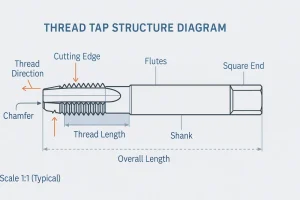
The core function of a tap is defined by its operating principle:
- Cutting Principle (Cut Taps): These taps generate threads by shearing and removing material (producing chips) via sharp cutting edges. Cut taps are versatile and suitable for a wide range of materials, including hardened and brittle metals.
- Forming Principle (Forming Taps): Also known as roll taps or chipless taps. They work by intense radial pressure, displacing and plastically deforming the material into the thread shape, resulting in zero chips. This process work-hardens the surface, producing threads typically 20%−30% stronger, but the tool is strictly limited to highly ductile materials (e.g., aluminum, low-carbon steel).
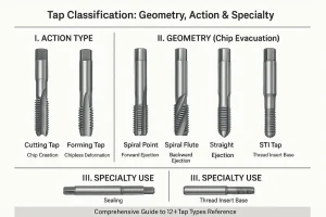
Tap Types
Understanding the structural geometry of each tap type is crucial for predicting its chip evacuation performance and selecting the right tool for the job. Tap designs are segmented by geometry, function, and the specific thread form they are intended to create.
Common Industrial Tap Types
Spiral Point Taps (Gun Taps)
The Spiral Point Tap features flutes that are only partially grooved along the body, with a primary cutting action concentrated on an angled shear face at the front end. This geometry is highly effective at driving the severed chips forward and out of the hole. Spiral Point Taps are thus the optimal choice for through-hole applications, allowing for high cutting speeds and efficient machining.
Spiral Flute Taps
Spiral Flute Taps are characterized by continuous helical grooves, typically featuring a high helix angle (35∘ to 45∘). This design actively lifts chips backward and upward, extracting them from the hole. This reverse evacuation mechanism is essential for blind-hole tapping and is the superior choice for machining sticky, stringy materials (like stainless steel) where chip congestion is the primary risk factor.
Straight Flute Taps
Straight Flute Taps have parallel flutes, resulting in low chip evacuation efficiency. Chips primarily accumulate within the flutes. This design is best suited for brittle materials (e.g., cast iron, brass) that produce short, segmented chips that do not easily jam the tap.
Forming Taps (Roll Taps)
Forming taps create threads through plastic deformation rather than cutting. They eliminate chip management issues and produce threads with enhanced strength due to surface work-hardening. However, they require highly controlled process parameters and tighter pilot hole tolerances.
Pipe Taps
Pipe taps are specialized tools used to machine threads into pipe fittings or valves. They include Taper Pipe Taps (NPT/BSPT), which create a tapered thread for fluid- or gas-tight sealing, and Straight Pipe Taps (NPSF/NPSM) for non-sealing connections.
Hand Tap Set Components
Manual tapping utilizes a set of three tools defined by their chamfer length, designed to distribute the cutting load: Taper Tap (long chamfer, for starting), Plug Tap (medium chamfer, for the main cut), and Bottoming Tap (short chamfer, for finishing the thread deep into a blind hole).
Specialized Tap Types
While standard tap types serve most applications, several specialized designs are critical for niche industrial purposes:
- STI Taps (Screw Thread Insert): Designed to cut oversized internal threads specifically for the installation of wire-thread inserts (Heli-Coil), commonly used in aluminum housings to restore or reinforce worn threads.
- Nut Taps: Characterized by a long shank and long-chamfered, straight-flute geometry, optimized for high-volume, continuous through-hole tapping in nut and fastener production.
- Interrupted Thread Taps (Chip Breaker Taps): Feature cutting edges that are segmented or intentionally removed to break chips into smaller segments, drastically reducing clogging in tough or ductile materials.
- Trapezoidal (Acme) Taps: Used for producing power transmission threads with trapezoidal profiles, ensuring smooth motion and high load capacity in lead screws or actuators.
- Left-Hand Taps: Produce left-handed threads used in rotating machinery to prevent self-loosening under operational torque.
- Combination Taps: Integrate drilling and tapping in a single pass, ideal for optimizing cycle time in automated production lines.
Sizing & Tolerance
The foundation of a reliable internal thread lies in accurate pilot-hole preparation and strict adherence to international tolerance classes. Even minor dimensional deviations can drastically increase torque, tool wear, or result in stripped threads.
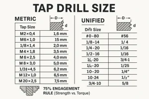
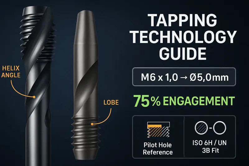
Pilot Hole Size Chart (≈75% Thread Engagement)
🧮 Engineering Note: The “75% thread engagement” rule achieves near-maximum strength while keeping tapping torque within safe limits. Engineers should ensure that the pilot hole diameter tolerance is tightly controlled, as torque rises exponentially when engagement exceeds 80%, often leading to tap breakage.
Thread Tolerance Classes (Fit & Interchangeability)
| Standard | Class | Fit Type | Description | Application |
| Metric (ISO) | 6H | Normal Fit | Standard tolerance, zero allowance for an optimal fit. | Most common fit for general bolts and screws. |
| 7H | Loose Fit | Slightly looser fit to compensate for subsequent plating or coating. | After surface finishing or large components. | |
| Unified (ANSI/ASME) | 2B | Standard Fit | Normal fit, allows for smooth assembly and clearance. | Industrial and mechanical components. |
| 3B | Precision Fit | Minimal clearance/play, requires strict control on tap wear. | Aerospace and high-precision assemblies. |
Common Sizing Errors and Risks
| Condition | Cause | Consequence | Prevention / Corrective Action |
| Undersized Hole | Drill smaller than spec | Excessive torque, immediate tap breakage. | Use verified drill charts; inspect pilot hole diameter. |
| Oversized Hole | Drill too large | Weak thread, pull-out under load. | Verify drill calibration; use the next smaller nominal size. |
| Worn Tap | Tool geometry degraded | Poor thread finish, undersized pitch diameter. | Replace or regrind tap based on prescribed tool life cycle. |
| Improper Tolerance | Selected wrong class (e.g., 5H instead of 6H) | Poor fit or loose assembly, galling. | Verify required class with Go/No-Go gauges. |
How to Choose the Right Tap Size and Tolerance
Selecting the proper tap size and tolerance class is not merely a matter of referencing a chart—it requires balancing strength, assembly requirements, and production efficiency.
1. Match Tap Size to Material Properties
- Ductile materials (e.g., aluminum, mild steel): Use standard 75% thread engagement to maximize strength without excessive torque.
- Hard or brittle materials (e.g., cast iron, hardened steel): Reduce engagement to 60%−65% to prevent tool breakage.
- Soft metals (e.g., copper, brass): May use smaller engagement (≈70%) to avoid deformation.
2. Consider the Function of the Assembly
- High-strength or load-bearing joints: Choose closer fits such as ISO 6H or UN 3B to ensure maximum contact.
- Parts requiring easy disassembly or coated surfaces: Choose looser fits such as ISO 7H or UN 2B.
- Sealing or pressurized systems: Use tapered threads (e.g., NPT, BSPT) for self-sealing engagement.
3. Align Tap Tolerance with the Fastener Class
Always verify the fastener tolerance before tapping. For example, pairing a 6H internal thread with a 6g bolt ensures a standard Class 2 fit under ISO standards. Using mismatched tolerance grades can result in loose or interference fits, leading to premature thread failure.
4. Verify Pilot Hole Accuracy
Even a ±0.05mm deviation in the pilot hole diameter can dramatically change torque and thread quality. Use calibrated drills and reamers to maintain consistency, especially in CNC production lines.
🧩 Pro Tip: When in doubt, start with a slightly larger pilot hole and measure the resulting thread with a Go/No-Go gauge. It’s easier to correct a loose fit than to recover from a broken tap.
Tapping Process & Tool Technology
Successful tapping requires synchronizing machine control with the physical limitations of the tool and material, often relying on advanced tooling technology.
Process Control and Execution
- Alignment and Rigid Tapping: For CNC operations, Rigid Tapping is non-negotiable. It electronically synchronizes the spindle speed and feed rate (f= pitch × RPM), eliminating damaging axial stress on the tap. Prior to tapping, the hole entrance must be chamfered to protect the first thread and guide the tap.
- Lubrication and Cooling: Cutting taps require ample, correctly specified cutting fluid for heat reduction and chip flushing. Forming taps demand specialized high-pressure tapping oil to withstand the intense frictional contact.
- Speed and Feed Optimization: Tapping speeds are significantly lower than drilling speeds. The correct parameters depend entirely on the tap’s base material and coating.
Tool Technology: Base Materials and Coatings
The tap’s capability is directly linked to its construction:
- Base Materials: HSS-Co (Cobalt) provides improved hot hardness for stainless steel. Solid Carbide provides maximum rigidity and wear resistance for hardened steels and abrasive materials.
- Coatings: Coatings like TiAlN (Aluminum Titanium Nitride) are essential for high-heat environments, as they improve tool life and permit higher surface speeds by resisting oxidation and transferring heat effectively.
Process Quality Control and Troubleshooting
Managing tool wear and swiftly addressing common failures are key to controlling production costs and maintaining quality.
Common Failures and Troubleshooting
| Risk/Problem | Indication | Solution & Maintenance |
| Tap Breakage | Sudden torque overload. | Cause: Undersized pilot hole, chip clogging, misalignment. Safe Removal: Use Electrical Discharge Machining (EDM) or ultrasonic methods to preserve surrounding threads. |
| Poor Thread Quality | Rough surface finish, threads fail gauge inspection. | Inspect the tap’s cutting edges (wear); confirm the correct cutting fluid and process parameters are used. |
| Stripped/Weak Threads | Thread gauge shows undersized engagement. | Cause: Pilot hole diameter is too large (below 60% engagement). Recheck drill chart and adjust hole size immediately. |
Quality Detection and Tool Maintenance
- Quality Check: Finished threads must be verified using Go/No-Go thread gauges to ensure they conform to the specified tolerance (6H,2B).
- Maintenance: Only cutting taps can be professionally reground to restore the cutting edge. All taps, especially precision-coated tools, must be stored with anti-rust oil and protected from mechanical damage.
Conclusion
Successful thread machining is the result of precise planning and rigorous execution. By mastering the right tap type, tolerance standard, and process control techniques, manufacturers can minimize failure rates and achieve superior thread quality and production efficiency.
Master the nuances of pilot hole sizing and tolerance standards to ensure reliable, high-integrity thread production. Explore our comprehensive catalog of High-Performance Taps today, or contact our sales team to Request a Quote for your next high-volume tooling requirement.
Tapping FAQ
What is the primary difference between spiral point and spiral flute tap geometries?
A: The difference lies in chip control: Spiral Point (Gun) Taps eject chips forward, making them ideal for through-holes. Spiral Flute Taps lift chips backward, which is essential for blind-holes and sticky materials like stainless steel.
When should I choose a Forming Tap over a Cutting Tap?
A: You should choose a Forming Tap only for highly ductile materials (e.g., aluminum, low-carbon steel) when you require a chipless process and 20%−30% stronger threads due to surface work-hardening. For all other materials, a Cutting Tap is required.
What is the key engineering rule for determining the pilot hole size?
A: The critical rule is the 75% Thread Engagement standard. This specific engagement percentage provides near-maximum thread strength while simultaneously keeping tapping torque safely below the threshold that causes catastrophic tap breakage.
What are the top three causes of tap failure or breakage?
A: The majority of failures result from excessive torque. The three leading causes are: undersized pilot holes (too much material to cut), chip clogging (flutes are packed with chips), and misalignment (a lack of rigid tapping or poor machine setup).
What is the safest method for removing a broken, hardened tap?
A: The safest, non-contact method that preserves the surrounding threads is Electric Discharge Machining (EDM). This process disintegrates the hardened tap material using an electrode, avoiding the axial forces that could further damage the part.