
In the realm of modern subtractive manufacturing, milling remains the core pillar for realizing complex geometric features and precise dimensional control. With the rapid advancement of machine tool technology and the continuous evolution of cutting theories, milling has transformed from basic surface finishing into a diversified process system—one that spans from high-volume stock removal to micron-level profile refinement.
A deep understanding of the unique logic behind various milling operations is not only a prerequisite for optimizing machining efficiency but also essential for enhancing structural integrity and service reliability. This article systematically outlines the physical essence and typical application scenarios of 15 mainstream milling methods, providing a clear reference for engineers during process planning and tool selection.
What is Milling?
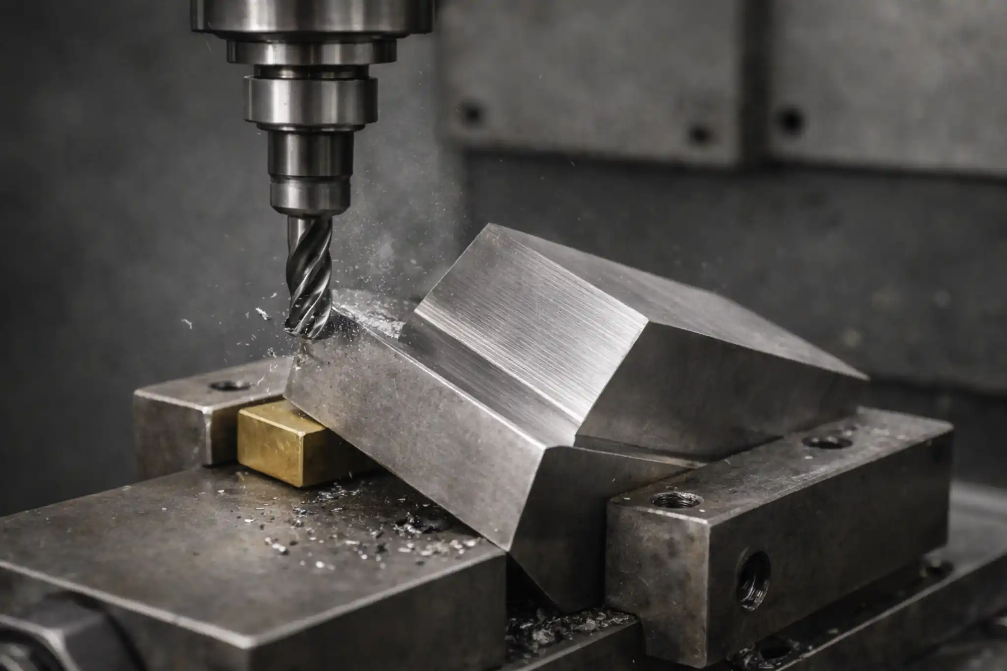
In essence, milling is a subtractive manufacturing process that removes excess material from a workpiece using a rotating multi-point cutter. Unlike turning, where the workpiece rotates against a stationary tool, the core of milling lies in the precise combination of high-speed tool rotation (primary motion) and the feed motion (secondary motion) of the workpiece or tool along multiple axes.
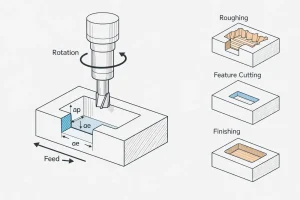
The physical logic of this process is defined by “interrupted cutting.” Each tooth on the cutter alternately engages and disengages from the material during rotation, producing discrete chips. By controlling this interaction frequency, depth of cut, and the toolpath, milling can produce anything from simple flat surfaces to extremely complex spatial geometries with high precision. It is this formidable control over three-dimensional space that makes milling the most versatile and widely utilized manufacturing method in the industrial world.
Fifteen common milling types
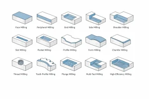
Isometric line drawing summarizing 15 common CNC milling operations, with the highlighted blue areas showing the typical machined feature of each process.
In actual production, selecting the correct milling approach is the prerequisite for ensuring both efficiency and precision.
By conducting a deep analysis of the cutting mechanisms and application scenarios of various processes, we have summarized the following 15 most commonly used milling types. These operations cover the entire spectrum from fundamental surface machining to the forming of complex functional features, serving as essential tools for engineers during process planning.
Overview of 15 Milling Operation Types
| Milling Type | Functional Description | Key Technical Feature | Primary Application | |
| 1 | Face Milling | Large-area surface leveling used to establish primary precision datums. | Large diameter; spindle axis perpendicular to the work surface. | Large flat faces, engine block mating surfaces. |
| 2 | Peripheral Milling | Utilizes circumferential edges to ensure straightness along long spans. | Spindle axis parallel to the work surface; peripheral cutting. | Plate edge trimming, side walls of long components. |
| 3 | Side Milling | Precise finishing of vertical walls to ensure strict perpendicularity. | Radial tool engagement; side-edge traversing. | Precision side walls, boss features. |
| 4 | End Milling | Versatile machining combining axial plunging and horizontal traversing. | Multi-axis movement; bottom and side edges working in tandem. | Closed pockets, irregular 2D/3D shapes. |
| 5 | Shoulder Milling | One-pass machining of a standard 90° step or vertical shoulder. | Simultaneous cutting by bottom and side edges. | Mounting seats, machine tool guide rail shoulders. |
| 6 | Slot Milling | Creating continuous linear channels with parallel side walls. | Linear path; full-width envelope cutting. | Keyways, T-slots, hydraulic flow channels. |
| 7 | Pocket Milling | Layered material removal and corner clearing within a closed boundary. | Closed boundary; central entry followed by outward expansion. | Weight-reduction pockets, internal functional recesses. |
| 8 | Multi-Tool Comb. | Integrated machining of multiple surfaces in a single stroke. | Multiple cutters of varying sizes mounted on a single arbor. | Mass production, engine cylinder heads, long guide rails. |
| 9 | Form Milling | Direct replication of complex cross-sections using specialized tool profiles. | Non-standard cutting edge geometry replicated onto the part. | Semicircular grooves, specific gear tooth gaps. |
| 10 | Chamfer Milling | Removing sharp edges and machining lead-in bevels for assembly. | Angled cutting edge sweeping along the workpiece periphery. | Deburring, assembly lead-ins, edge protection. |
| 11 | Profile Milling | Tracing intricate 2D/3D trajectories to define the final external geometry. | Multi-axis synchronization; path-following scanning. | Mold cores, aerospace structural ribs, housings. |
| 12 | Thread Milling | Precision machining of internal/external threads via helical interpolation. | 3-axis synchronization; helical climbing feed. | High-value components, difficult materials, large diameters. |
| 13 | Tooth Profile Milling | Specialized indexing-based machining for mechanical transmission teeth. | Form cutters synchronized with indexing mechanisms. | Gears, splined shafts, sprockets. |
| 14 | CAM-Optimized HEM | Algorithm-driven high-speed removal via constant tool engagement angles. | CAM-controlled paths; high feed rates with shallow depths of cut. | Heavy-duty roughing, high-efficiency material removal. |
| 15 | Plunge Milling | Vertical-feed removal utilizing longitudinal rigidity for deep features. | Axial force concentration; suppression of radial vibrations. | Deep cavities, heavy-duty roughing in unstable setups. |
1. Face Milling
The removal of bulk stock is typically achieved by sweeping a face milling cutter across the workpiece surface. As the cutting edges rotate in a plane perpendicular to the spindle, this transverse path rapidly levels the raw material and compensates for any flatness errors.
This method is the preferred choice for establishing precision datums. The resulting planarity directly dictates the locating accuracy for all subsequent assembly and machining operations.
2. Peripheral Milling
Utilizing the outer circumferential edges of the tool for a rolling feed is the core feature that distinguishes peripheral milling. During the process, the spindle remains parallel to the machining surface while the side of the cutter acts like a roller, making it exceptionally suited for trimming the edges of long-span components.
This approach excels at maintaining thickness consistency and lateral straightness, and it is frequently employed for heavy-duty roughing or the final shaping of plate contours.
3. End Milling
Through a coordinated combination of axial plunging and horizontal traversing, end milling grants the tool the ability to “walk” within the material. The synchronized action of the bottom and side edges allows it to carve out pockets, closed slots, or complex irregular boundaries directly from the solid substrate.
This flexibility makes it the standard solution for machining weight-reduction holes, deep recesses, and winding contours, easily accommodating diverse spatial requirements inside a part.
4. Side Milling
Side milling centers on the precise refinement of vertical surfaces through lateral tool engagement. The side edges of the cutter traverse along the workpiece wall, and by adjusting the radial depth of cut, features such as bosses, shoulders, or narrow slots are brought to their target dimensions and surface finish.
This process addresses lateral areas inaccessible to face milling, ensuring strict perpendicularity and a precise transition where vertical features meet the base.
5. Shoulder Milling
Relying on the synchronized cutting of both bottom and side edges in a single pass, shoulder milling generates a standard 90° step along the material edge. This integrated design eliminates the cumbersome need for separate horizontal and vertical processing, allowing two perpendicular planes to be produced simultaneously.
Commonly applied to machining mounting seats, clearance grooves, or multi-tiered support surfaces, this method significantly boosts forming efficiency while ensuring geometric consistency at the corner.
6. Slot Milling Operations
The tool advances linearly deep into the material, utilizing an enveloping action of the side and bottom edges to open continuous channels. The resulting width of the longitudinal space is directly determined by the cutter diameter, while the depth is precisely controlled by the axial feed.
It serves as the standard means for creating keyways, T-slots, and hydraulic flow channels. While efficiently stripping material, it ensures strict parallelism between the opposing sidewalls of the slot.
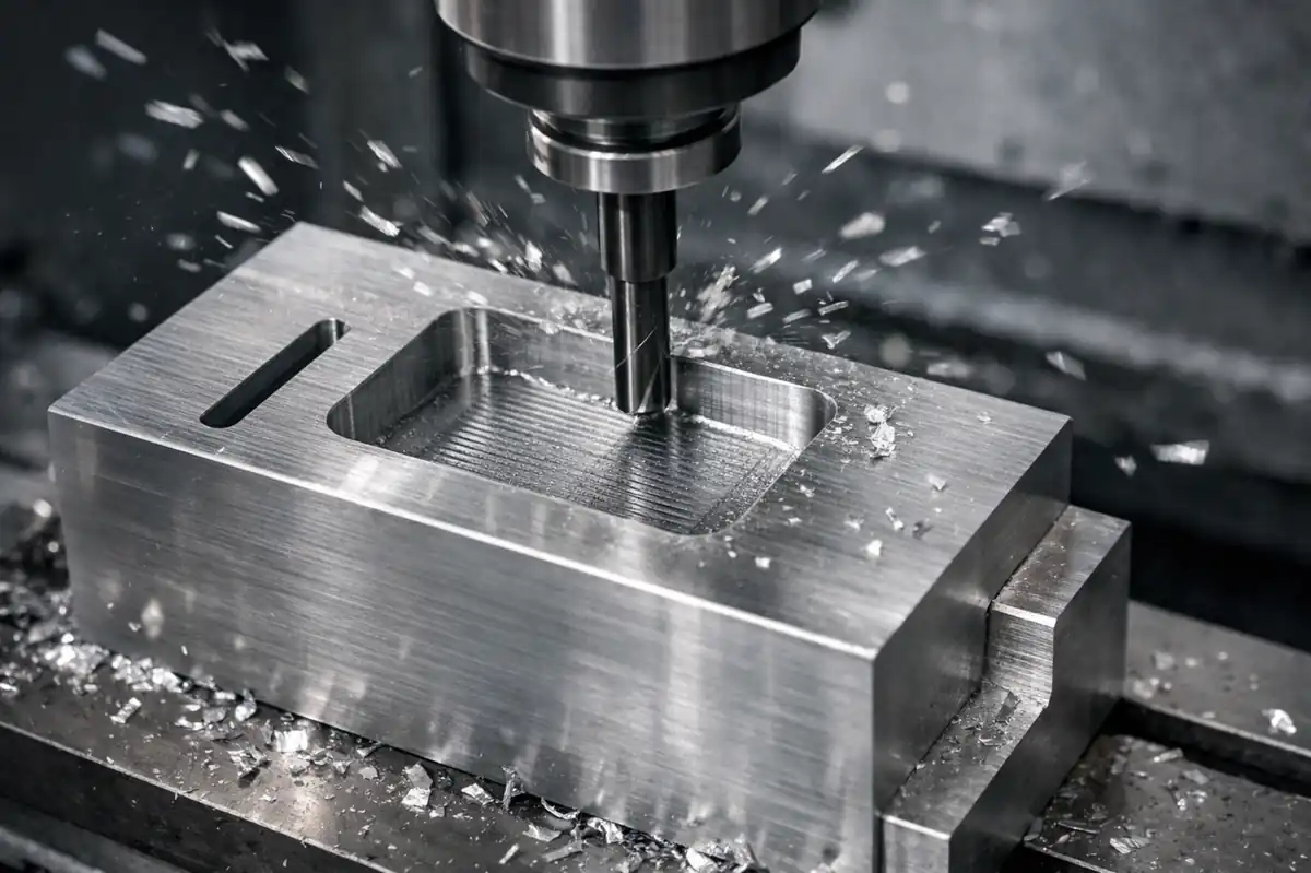
7. Pocket Milling
Within a predefined closed boundary, the cutter clears out internal stock layer by layer through multi-layered reciprocating paths. The process typically begins with a central axial entry and subsequently expands outward until the specific depth and floor profile of the recessed space are fully realized.
This method is critical for achieving structural weight reduction and functional internal recesses. It not only manages floor flatness but also ensures precise corner clearing or filleting through fine-tuned path control.
8. Profile Milling
The cutter follows a continuous trajectory along the internal or external boundaries of a part, utilizing multi-axis synchronization to trace intricate geometric outlines. Whether it involves 2D curves or 3D surface scanning with a ball-end mill, profile milling ensures a smooth and fluid transition across the entire cutting path.
It directly defines the final exterior of the workpiece and stands as an indispensable forming process for machining mold cores, aerospace structural ribs, and streamlined housings.
9. Form Milling
Specialized form cutters replicate their complex edge profiles directly onto the workpiece surface through a simple feed motion. This approach eliminates the need for complex path interpolation, requiring only a single pass to achieve a cross-sectional feature that perfectly matches the tool’s geometry.
Form milling significantly enhances the production efficiency of semi-circular grooves, gear tooth structures, or specific radial surfaces, ensuring high consistency across large production batches.
10. Chamfer Milling
A chamfering tool with a specific inclination angle sweeps along the workpiece edges, transforming sharp corners into controlled beveled transitions. This action can be executed along linear edges or smoothly guided around hole perimeters and complex contoured corners.
Beyond improving part safety through deburring, it provides essential lead-in slopes for subsequent assembly and enhances the edge’s durability against impact during its service life.
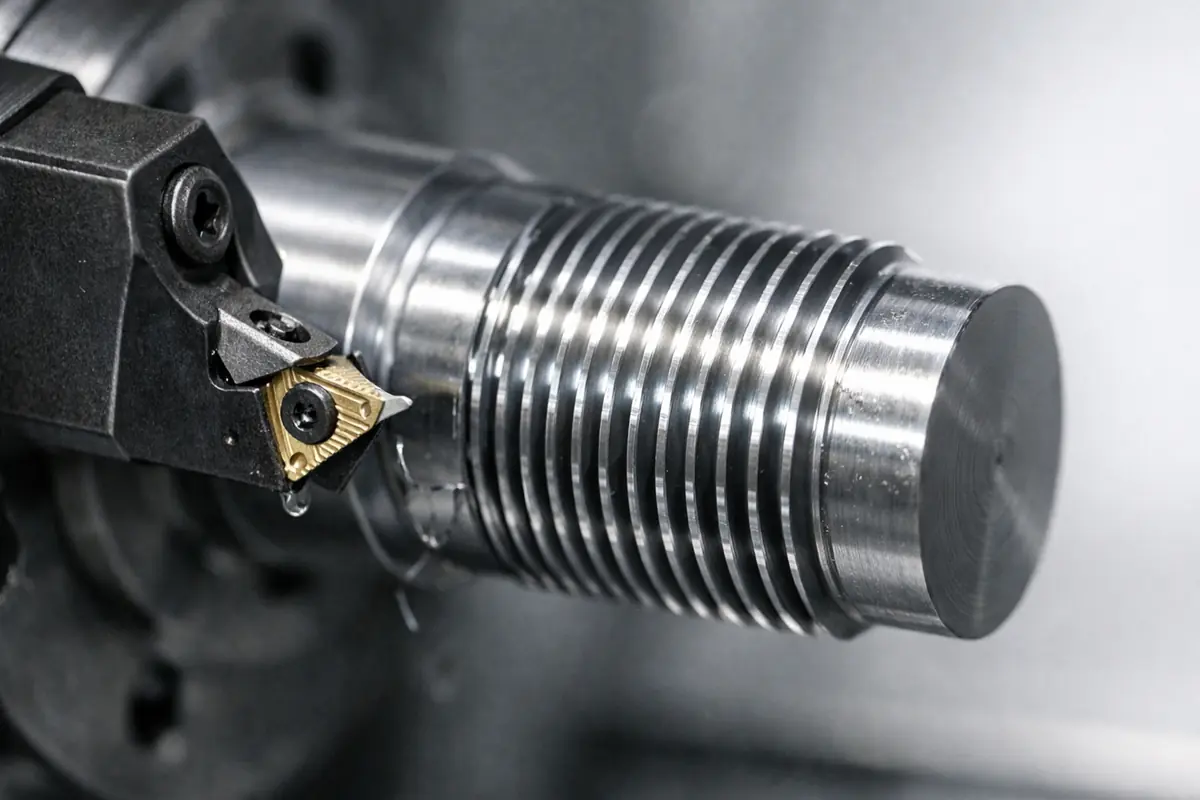
11. Thread Milling
The tool rotates while precisely climbing along a helical path, using its side teeth to carve standard thread trajectories into hole walls or cylindrical surfaces. This synchronization of rotation and helical feed makes the threading of large diameters or difficult-to-machine materials far more controllable.
With the ability to adjust dimensions via programming and a minimal risk of tool breakage, it has become the reliable choice for machining internal and external threads on high-value molds or precision components.
12. Tooth Profile Milling
Through the coordination of indexing mechanisms and form cutters, specific tooth spaces are machined one by one into a cylindrical blank to meet mechanical requirements. Depending on precision needs, this can be performed via individual tooth cutting or continuous hobbing, ensuring each tooth profile possesses exact geometric parameters.
This is the core process for manufacturing gears, splined shafts, and sprockets. Its quality directly dictates the operational smoothness and load-bearing capacity of mechanical transmission systems.
13. Multi Tool Combination Milling
Multiple cutters of varying diameters or shapes are mounted in series on a single arbor, allowing a single pass to cover several machining surfaces simultaneously. This integrated cutting strategy consolidates multiple operations into one stroke, drastically compressing the overall production cycle.
This method is primarily targeted at mass-produced engine blocks or machine tool guide rails. By reducing the frequency of repeated clamping, it significantly minimizes positional errors between different machined features.
14. CAM-Optimized High-Efficiency Milling
These methods utilize optimized CAM algorithms to achieve rapid cycles of high feed rates and shallow depths of cut, while maintaining a constant tool engagement angle. This path strategy is designed to keep cutting forces stable and prevent excessive heat buildup in localized areas.
As a cutting-edge means of boosting productivity in modern manufacturing, these methods clear massive amounts of stock efficiently. They represent an advanced solution that shortens machining time while significantly extending tool service life.
15. Plunge Milling
Plunge milling removes material by advancing the tool vertically along the spindle axis, peeling away stock in a series of overlapping circular cuts similar to drilling. By concentrating the cutting forces in the machine’s strongest longitudinal direction, this method effectively eliminates radial vibrations common when tackling deep cavities or difficult-to-machine materials.
In the CAM environment, this “drill-style” strategy is a powerhouse for heavy-duty roughing. It is specifically suited for hollowing out exceptionally deep pockets, clearing corners with large stock, or achieving massive material removal rates under unstable clamping conditions—serving as an advanced solution for deep machining challenges in aerospace and large-scale mold manufacturing.
How to Select the Right Milling Process?
In complex machining tasks, selecting the optimal solution typically depends on a comprehensive evaluation across the following three dimensions:
- Geometric Features and Precision: Identify the core functional features of the part. Large-area surfaces prioritize face milling to establish datums, while closed cavities must rely on pocket or end milling. For high-precision vertical walls, the synchronized advantage of side and shoulder milling is the preferred choice.
- Efficiency and Material Removal: For high-volume stock removal, assess the suitability of peripheral milling or high-efficiency milling methods (such as trochoidal milling). In mass production, adopting form milling or multi-tool combination milling can significantly compress cycle times.
- Economy and Risk Management: Weigh the procurement costs of specialized cutters against the cycle times of universal tools. For high-value components, choosing thread milling—which offers lower risk and higher flexibility—often proves more economically secure than traditional methods.
Conclusion
The evolution of milling processes reflects the relentless pursuit of precision and efficiency in modern manufacturing. From fundamental face milling to complex five-axis profile tracking, every operation plays an irreplaceable role in realizing a part’s structural design. Process selection is not an isolated decision, but a balancing art of geometric accuracy, surface quality, and production cost.
A deep understanding of the physical essence and application boundaries of each milling method serves as the foundation for ensuring parts meet mechanical performance and reliability requirements. As high-efficiency algorithms and multi-tasking machining technologies become more prevalent, the future of milling will trend toward greater intelligence and integration.
If you are planning your next machining project, we invite you to re-evaluate these process combinations to explore the optimal path for maximizing production potential. For specific technical challenges, please contact our engineering team for customized support.