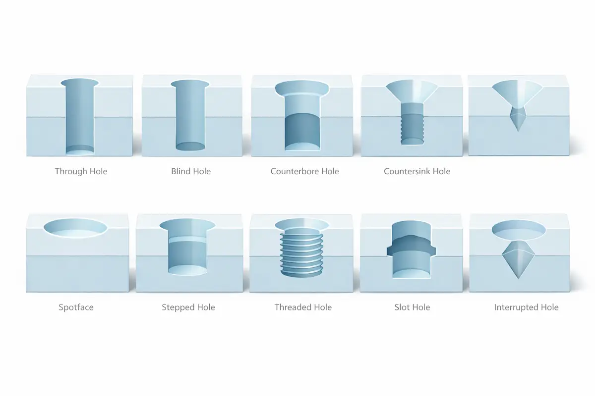

In precision manufacturing, an undercut is a recessed geometric feature that cannot be reached by a standard straight-shank cutting tool along the primary spindle axis. From O-ring grooves in hydraulic valves to T-slots in machine worktables, undercuts are essential for providing assembly clearance, reducing stress concentration, or creating secure positioning for seals.
Because these features reside in the “visual blind spots” of tool feeding, they demand specialized tooling and high technical standards for the manufacturing process. This guide analyzes undercut classifications, industrial applications, and Design for Manufacturability (DFM) principles.
What Is an Undercut in Machining?
From an engineering perspective, an undercut is a recessed structure where the opening dimension is smaller than the internal feature width. Its core purpose is to satisfy functional requirements, such as housing seals or snap rings and improving fatigue life by eliminating sharp corners.
In machining, an undercut is defined by “tool accessibility.” If a feature is obscured by the part’s own geometry, preventing a standard vertical tool from cutting it, it is classified as an undercut. This restricted accessibility dictates the use of specialized form tools or multi-axis equipment, making undercuts essential for complex mechanical functions like T-slot locking or annular sealing.
Common Types of Undercuts
The geometry of an undercut directly dictates the machining strategy and tool selection. In practical production, undercuts are generally categorized into several typical structures:
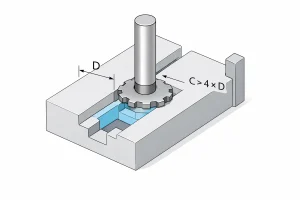
T-Slot Undercuts
This is the most classic undercut structure in the industry, widely used for mounting T-bolts on machine worktables. The machining process follows a “slot-then-expand” logic: a standard end mill first cuts a straight pilot slot, followed by a specialized disk-shaped T-slot cutter that enters the slot to expand the base horizontally.
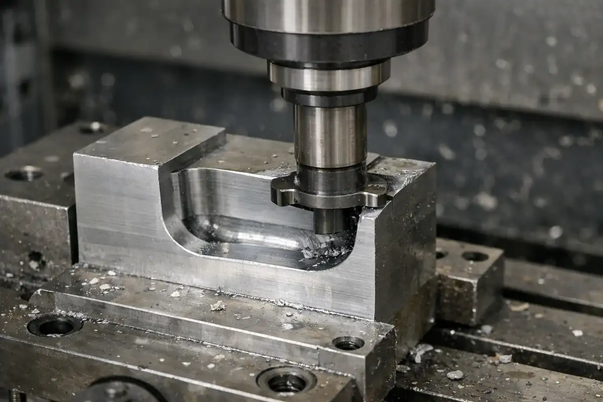
Side Undercuts
These structures are frequently found in aerospace weight-reduction pockets or complex housing interiors. Since the cutting zone is located deep within a sidewall, multi-axis machinery is typically required alongside “lollipop” cutters. Utilizing a ball-head diameter larger than the shank, the tool can enter narrow openings to hook out material from the side.
Dovetail Undercuts
Dovetail grooves feature angled sidewalls (typically 45° or 60°), creating an inverted cone shape with a narrow opening and a wide base. This geometry allows parts to nest together like puzzle pieces, serving as the core structure for self-centering and mechanical interlocking in precision guides and fixtures.
Groove-Type Undercuts
As the most common type of undercut, these are primarily used to house O-rings or snap rings. They are usually found on internal bore walls or shaft surfaces. Because the groove dimensions directly impact sealing performance, tolerance requirements are extremely strict to prevent fluid or air leaks.
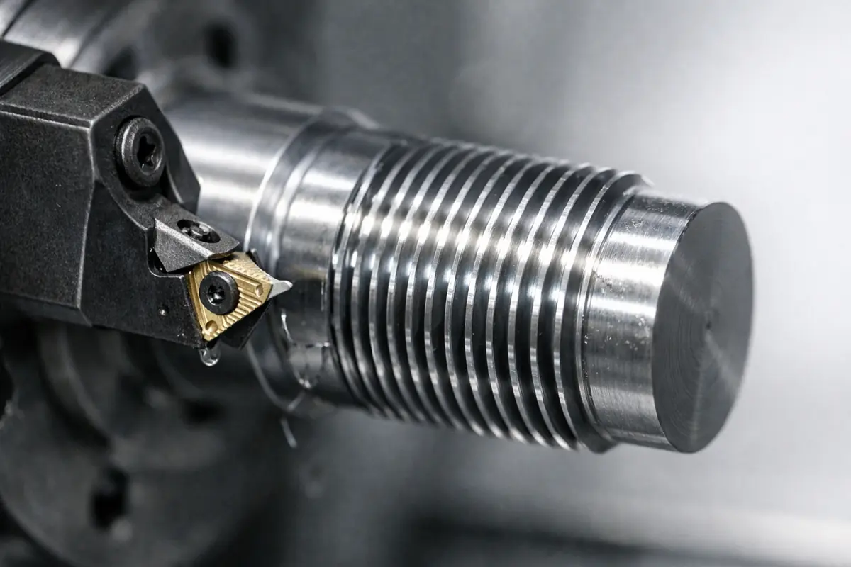
Thread Relief and Relief Undercuts
While small in size, these undercuts are critical mechanical details. A thread relief is cut at the end of a thread to provide the necessary “exit space” for the cutting tool, ensuring the thread is completed fully. Meanwhile, relief undercuts (or stress reliefs) at shaft shoulders are used to smooth out stress distribution, preventing the part from suffering fatigue fractures at sharp corners under load.
Specialized Tools for Undercut Machining
Selecting the right tool is the bridge between a blueprint and a finished product, directly impacting efficiency and surface finish.
T-Slot Cutters
The primary choice for T-slots and deep lateral grooves. Shaped like a small circular saw blade on a shank, the cutting edges are located on the circumference and both the top and bottom faces.
Dovetail Cutters
These feature an inverted cone structure with cutting edges at specific angles. Because the head is wider than the neck, they are specifically designed for machining precision guides and dovetail joints.
Lollipop Cutters
Named for their spherical head which is larger than the shank. The spherical cutting edge allows the tool to reach around edges to machine backsides or hidden 3D surfaces, making them a staple in 5-axis machining.
Internal Grooving Bars
Standard for machining internal O-ring grooves in turned parts. These rely on a slender bar to deliver a radial cutting edge inside a hole. Design must account for the bar’s clearance during entry and retraction.
Thread Relief & Necking Tools
Form tools designed to cut specific relief grooves. They eliminate machining blind spots and reduce stress concentrations, ensuring that mating parts like bearings or nuts can sit flush against the shoulder.
Common Applications in Mechanical Design
Undercuts provide irreplaceable mechanical value in achieving compact and high-performance structures:
- Hydraulic & Pneumatic Systems: Precision internal grooves house dynamic seals to prevent leakage under high pressure.
- Power Transmission: Thread reliefs and snap ring grooves on shafts enable secure axial positioning of bearings and gears.
- Precision Instruments: Dovetail guides allow for nano-level adjustment and positioning in optical platforms.
- Aerospace Components: Side undercuts remove redundant metal to achieve extreme weight reduction without compromising stiffness.
Challenges in Undercut Machining
While undercuts are highly attractive for functional design, they impose demanding requirements on the manufacturing process. Understanding these physical bottlenecks helps designers find the sweet spot between “ideal functionality” and “production cost.”
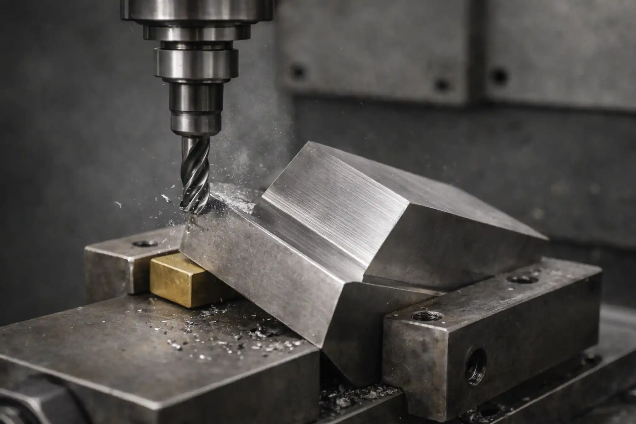
Tool Rigidity and Chatter
Undercut machining often requires the use of “thin-necked” or long-reach tools to access areas hidden deep inside a part or beneath a shoulder. In mechanical modeling, tool rigidity is inversely proportional to the cube of its overhang length. This means that even a slight increase in tool length results in a drastic drop in its ability to resist cutting forces.
This lack of stiffness easily triggers intense vibrations during cutting, known as “chatter.” This not only leaves visible ripple marks on the surface but can also cause micro-chipping of the tool edge, directly compromising the dimensional accuracy and service life of the component.
Chip Evacuation and Heat Accumulation
The recessed nature of an undercut creates a semi-enclosed space, posing a massive challenge for chip removal. If metal chips cannot escape smoothly, they accumulate in the groove and are repeatedly crushed and cut by the tool. This “secondary cutting” phenomenon generates significant frictional heat, causing tool temperatures to spike instantly.
Because traditional coolant sprays struggle to bypass obstructions and reach the hidden cutting zone, heat tends to build up locally. This not only accelerates the wear of tool coatings but can also cause critical sealing surfaces—such as O-ring grooves—to undergo thermal softening or micro-deformation, leading to potential sealing failures.
Inspection Blind Spots
There is a famous saying in precision manufacturing: “If you can’t measure it, you can’t make it.” Standard inspection tools, such as digital calipers or internal micrometers, often cannot reach hidden undercut regions due to structural limitations. This lack of direct visibility is a major pain point in quality control.
This forces the inspection process to rely on expensive custom Go/No-Go gauges or Coordinate Measuring Machines (CMM) equipped with specialized long-reach probes. Because the measurement process is difficult and requires dedicated fixtures or programming, it not only extends the production cycle but also significantly increases the cost of quality assurance.
Tool Path Complexity
Undercut machining is never a simple “in-and-out” operation. The tool must navigate like it is in a “maze”—precisely entering a narrow opening, moving into the cutting position, and then carefully retracting along a pre-defined safe path once the task is complete.
If the path planning is slightly off, the tool will collide with the overhanging structure during retraction, leading to tool breakage or even scrapping the part. This complex spatial logic places high demands on the skill of CAM programmers and the simultaneous movement precision of 5-axis machinery, serving as a hidden factor that drives up the machining time per part.
Design Tips for Machined Undercuts
Optimizing geometry during the design phase is the most effective way to reduce cost and technical risk. Below are the core strategies to improve the manufacturability of undercut features:
Align with Standard Tool Sizes
When planning groove widths, radii, or angles, always refer to standard tool catalogs. Utilizing standardized dimensions (such as 3mm or 6mm widths, or 45° and 60° dovetail angles) allows for the use of off-the-shelf tooling. This avoids the high costs associated with custom-made tools and prevents long lead times that can delay production by weeks.
Reserve Space for Tool Entry
Undercut tools typically need to enter through an opening before moving laterally to perform the cut. It is essential to ensure the entry diameter is larger than the tool head and to provide enough clearance for the tool shank to swing or travel. Proper simulation during the design phase prevents the tool from colliding with the part edges during entry or retraction.
Control Depth-to-Width Ratio
The ratio of the undercut depth to its opening width directly impacts machining stability. It is recommended to keep the undercut depth within 1.5 times the opening width. Exceeding this ratio necessitates the use of ultra-slender tool shanks, which significantly reduces tool rigidity and triggers vibration (chatter), leading to poor surface finishes or tool breakage.
Define Critical Surfaces Clearly
Specify clearly on the technical drawings which surfaces are functional, such as seal seats for O-rings. By relaxing tolerance requirements on non-functional relief areas, you allow the machinist to optimize tool paths and increase cutting speeds, which can substantially reduce the per-part production cost.
Conclusion
Undercuts are a powerful tool for balancing mechanical performance with structural compactness. Successful design requires a deep understanding of manufacturing accessibility. By identifying types early, matching standard tooling, and conducting a thorough DFM evaluation, engineers can achieve high-quality results at a lower cost.
Before finalizing your drawings, a professional process review is recommended. Contact our engineering team today to upload your 3D models for a technical feasibility assessment and a detailed quote.