
What Does “5‑Axis” Actually Mean?
In CNC machining, the term “5-axis” refers to the number of directions in which a cutting tool—or sometimes the part itself—can move and rotate. Specifically, it describes three linear axes (X, Y, and Z) and two additional rotational axes (usually A, B, or C), allowing the machine to orient and position the tool or part at nearly any angle.
This five-axis capability significantly extends the motion range beyond what 3-axis or even 4-axis machines can achieve. It enables more efficient tool paths, easier access to complex part features, and reductions in setup time. However, it’s important to clarify that “5-axis” does not refer to a specific machining process—it’s a description of the machine’s kinematic structure and its degrees of movement.
Understanding what these five axes are—and how they work together—is essential not just for machine operators, but also for engineers, designers, and procurement professionals. For a comprehensive understanding of 5-axis machining, including its core principles, advantages, and applications, explore our [ultimate 5-axis machining guide]
A Brief History of Multi‑Axis Machining
The concept of multi-axis machining dates back to the 1950s and 1960s, when aerospace and defense industries began demanding more complex components with tighter tolerances and curved surfaces. Early CNC machines operated on three linear axes—X, Y, and Z—which limited tool orientation and required multiple setups for angled features. As part complexity grew, manufacturers explored ways to improve flexibility by adding rotational motion.
This led to the development of 3+2 machining, where a part could be positioned using two additional axes—A and B or A and C—but cutting would still occur using only three axes. These were known as “positioning” systems rather than fully interpolated five-axis machines.
True simultaneous 5-axis machining emerged in the 1980s and 1990s with advances in servo control, computer-aided manufacturing (CAM) software, and feedback systems. These machines allowed continuous, coordinated movement across all five axes, enabling highly efficient tool paths and smoother surface finishes. Today, 5-axis systems have become mainstream in industries ranging from mold making to medical implants, not just aerospace. The evolution of axis control paved the way for more intelligent motion strategies and increasingly compact, versatile machine designs.
Degrees of Freedom: 5 Is the New Milestone
In motion control and kinematics, “degrees of freedom” (DOF) refer to the number of independent movements an object or system can perform. A rigid body in three-dimensional space has six degrees of freedom: three translational (along X, Y, and Z axes) and three rotational (around those same axes—A, B, and C). Robotic arms often utilize all six for full spatial control.
However, in CNC machining, the goal is not general motion, but precise tool engagement with a static workpiece or one mounted on a fixture. In this context, five degrees of freedom are typically sufficient. The tool must move in X, Y, and Z to reach any point in space and rotate around two axes to align itself for optimal cutting orientation. The sixth axis—rotation around the tool’s own Z-axis—is rarely needed in most machining operations and may even be undesirable due to spindle geometry.
This makes five-axis machines the sweet spot: they provide nearly full spatial access to complex features while maintaining rigidity, simplicity, and controllability. Understanding this milestone in motion capability helps clarify why “5” is not arbitrary—it reflects a practical engineering boundary between mobility and manufacturability.
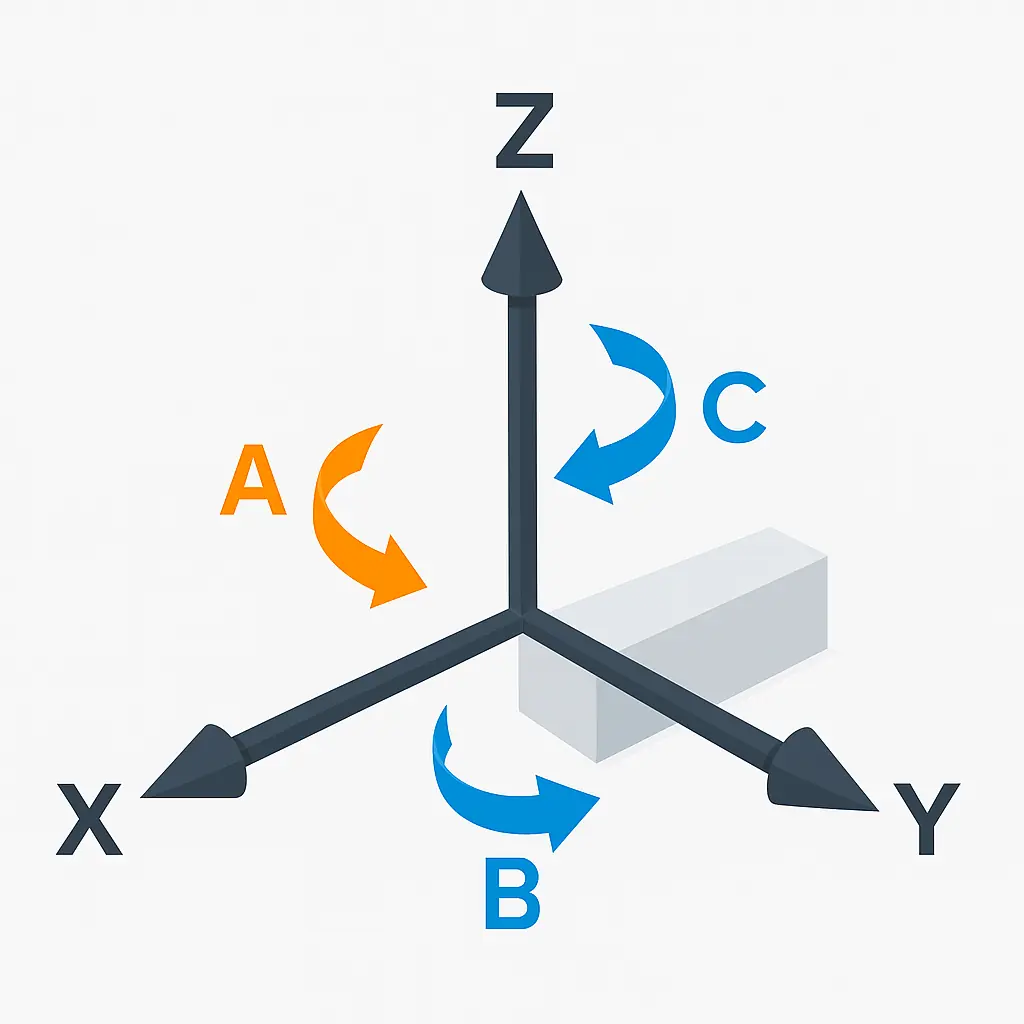
The Three Linear Axes: X, Y, and Z
Every CNC machine, regardless of how advanced, begins with the three fundamental linear axes: X, Y, and Z. These axes define movement along straight lines in three-dimensional space. The X-axis typically represents left-to-right motion, the Y-axis covers front-to-back movement, and the Z-axis moves the tool or table up and down. Together, they form the Cartesian coordinate system that underpins all CNC positioning logic.
In a vertical machining center (VMC), the spindle is mounted vertically and the table moves in the X and Y directions while the spindle head moves along Z. In horizontal machining centers (HMCs), the spindle is oriented horizontally, and the movement configuration may differ, sometimes with the table rotating or shifting along one of the linear axes. Gantry and portal-style machines often reverse the paradigm by moving the entire bridge structure across X or Y.
While the concept of linear motion may seem straightforward, misunderstanding axis orientation is a common source of design and programming errors—especially when switching between machine types. Clear awareness of how these three axes translate into physical movement is essential before adding rotational motion into the mix.
The Rotational Axes: A, B, and C
Beyond the three linear directions, CNC machines can rotate the tool or part around specific axes to reach angled surfaces and complex features. These rotational axes are designated as A, B, and C, and each corresponds to a rotation around one of the linear axes. Specifically, the A-axis rotates around the X-axis, the B-axis around the Y-axis, and the C-axis around the Z-axis.
In practical terms, these rotational motions allow the tool to tilt or the part to be spun into orientation for optimal machining. For example, a trunnion-style machine may use the A-axis to tilt the table forward and backward, while the C-axis spins it like a turntable. In contrast, a head-tilt machine may rotate the spindle using the B-axis to achieve angled cutting, with the C-axis providing rotary motion within the tool head.
Most 5-axis CNC machines incorporate two of the three rotational axes—usually A and C or B and C—depending on the machine’s design. It’s rare for a system to include all three simultaneously, as two are typically sufficient for positioning the tool in any desired orientation. Choosing which rotational axes to implement affects not only motion control and fixturing but also the complexity of programming and toolpath planning.
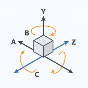
Illustration of the six-axis system in 5-axis CNC machines, including three linear and three rotational axes
3+2 vs. Simultaneous 5‑Axis: Why It Mattered
Not all 5-axis machines operate the same way. Broadly speaking, there are two types of 5-axis motion strategies: 3+2 positioning and simultaneous 5-axis interpolation. Understanding the difference between the two is crucial for interpreting machine capability and application suitability.
In 3+2 machining, the two rotational axes (usually A and C) are used to orient the part at a fixed angle before cutting begins. The toolpath itself is then executed using only the three linear axes (X, Y, Z). This method is highly effective for accessing angled features or multiple faces in a single setup and offers simpler toolpaths and lower computational demand. However, it lacks the fluidity required for highly contoured surfaces.
Simultaneous 5-axis machining, by contrast, allows all five axes to move at the same time. This enables continuous tool engagement with curved or freeform surfaces and allows optimal tool orientation throughout the cut. It dramatically improves surface finish, reduces tool wear, and shortens machining cycles—but at the cost of increased programming complexity and machine tuning requirements.
The shift from 3+2 to full 5-axis interpolation marked a major leap in CNC capabilities. It allowed not only more complex parts to be machined, but also improved overall efficiency in high-precision, multi-surface operations.
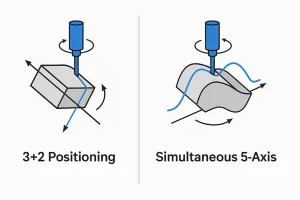
Comparison of 3+2 and simultaneous 5-axis machining, showing tool path and motion differences
Axis Layouts in Machine Designs
While all 5-axis machines offer motion in five directions, the way those axes are arranged varies significantly depending on machine design. Most commercial systems use one of three main layouts: trunnion-table, swivel-head, or a hybrid head-table combination. Each layout affects machine footprint, part size limits, accessibility, and programming strategies.
The trunnion-table design integrates the A-axis (tilt) and C-axis (rotation) directly into the worktable. The part is mounted on the table, which tilts forward/backward and spins like a turntable. This setup is compact and highly rigid, making it ideal for smaller parts requiring aggressive cuts or deep cavities. However, its build envelope limits clearance for tall or heavy components, especially when tilted.
The swivel-head configuration places the rotational axes in the spindle. The tool head tilts via the B-axis and rotates via the C-axis, while the workpiece stays fixed. This is often better for large, heavy parts that would be difficult to rotate. It also provides more consistent tool access regardless of part geometry.
A hybrid head-table system combines rotation in both the table and the spindle, offering maximum flexibility. It can handle a wider variety of geometries but comes with higher machine cost and more complex maintenance. Understanding these layouts helps engineers and buyers choose systems that align with their specific part profiles and production goals.
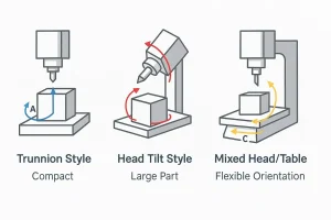
Three common 5-axis machine designs: Trunnion, Head Tilt, and Head-Table configurations
Why Axis Terminology Matters
Understanding axis terminology isn’t just for machinists or CAM programmers—it’s fundamental for anyone involved in the design, specification, or procurement of precision-manufactured parts. When engineers understand how the X, Y, Z, A, B, and C axes function and interact, they can design parts that are more manufacturable and easier to fixture. Avoiding undercuts that require tool tilting, aligning features along accessible planes, or orienting cavities for optimal spindle clearance all stem from a grasp of axis movement.
For procurement teams or project managers, knowing what a supplier means when they say “5-axis capability” is equally critical. Does the vendor use 3+2 positioning or full simultaneous interpolation? What type of axis layout does their machine use, and does it align with your part geometry? These aren’t niche technicalities—they affect lead times, surface quality, and cost.
Even for quality control and reverse engineering roles, understanding axis structures helps in interpreting CMM setups or reorienting scanned parts. In short, axis literacy bridges the gap between design intent and real-world execution. It’s not about memorizing labels—it’s about communicating precision effectively.
Frequently Asked Questions
What are the 5 axes in a CNC machine?
The five axes refer to three linear directions—X (left/right), Y (front/back), and Z (up/down)—plus two rotational axes, commonly A (rotation around X) and C or B (rotation around Z or Y). These allow the tool or part to be moved and tilted for complex machining angles.
Is the C-axis always used in 5-axis systems?
Not necessarily. Different machines use different combinations of rotational axes. Some use A and C, while others use B and C, depending on whether the rotation is built into the table or the spindle head. What matters is that the machine supports motion in five independent directions.
Do I always need simultaneous 5-axis motion?
No. For many parts, 3+2 machining—where the tool is positioned at an angle using the two rotary axes, but cutting occurs with three linear axes—is sufficient. Simultaneous 5-axis is more powerful but also more complex and typically reserved for freeform surfaces or critical contours.
Explore More About 5-Axis Machining
Now that you understand how the five axes work and how they impact machine motion, you’re better equipped to evaluate manufacturing capabilities and part complexity. But structure is only part of the story. To see how 5-axis motion is applied in real-world production—including tool paths, fixture planning, and advanced machining strategies—visit our in-depth guide: 👉 What Is 5-Axis Machining?
Or, if you’re ready to discuss a project that requires multi-axis capabilities, feel free to contact our engineering team for advice on part feasibility and precision options.