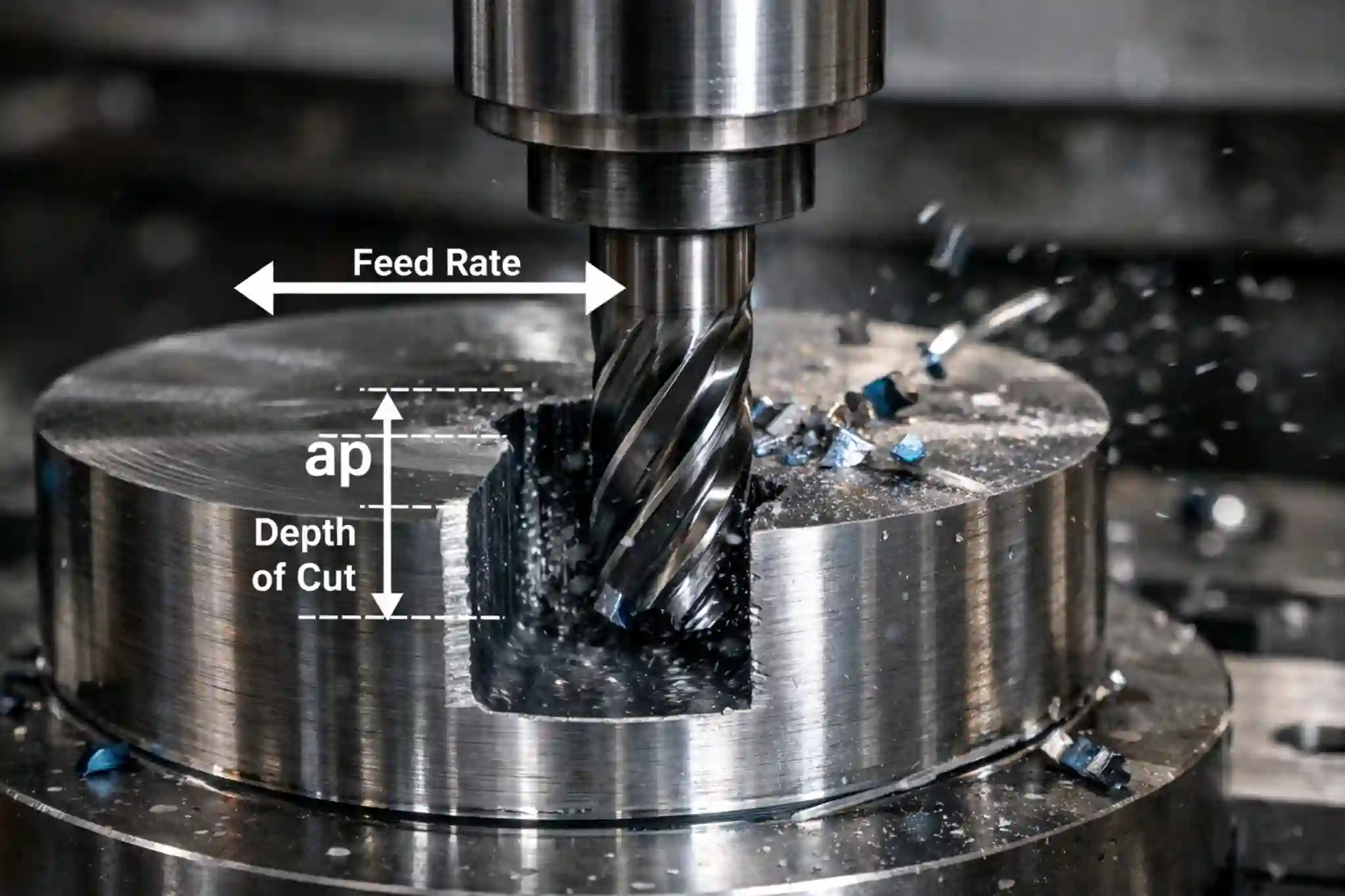

SFM is a commonly used speed parameter in machining that describes the actual cutting speed of the tool across the workpiece surface. It is not only a value used to calculate spindle speed, but also a factor that affects tool life, surface finish, and machining efficiency.
This article will explain what SFM is, how it is calculated, how it differs from RPM, and how it affects actual machining performance.
What Is SFM in Machining?
SFM refers to the distance that the cutting edge travels across the workpiece surface in one minute, and it is a common way to measure cutting speed.
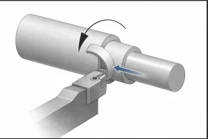
Unlike RPM, SFM focuses on the actual speed at the point of contact between the tool and the workpiece, so it is usually a more useful reference when setting machining parameters.
How Does SFM Affect the Machining Process?
In metal cutting, SFM (Surface Feet per Minute) directly affects the cutting conditions at the contact zone between the tool and the workpiece. As cutting speed changes, cutting heat, tool wear, surface finish, and machining efficiency also change. Understanding the role of SFM helps achieve a better balance between efficiency, stability, and cost in actual machining.
Cutting Heat
SFM is one of the key factors that affect cutting heat. As cutting speed increases, friction and plastic deformation between the tool and the workpiece usually become stronger, and the temperature in the cutting zone rises accordingly.
Low SFM: When heat is insufficient, material is more likely to adhere to the cutting edge and form a built-up edge (BUE), which can affect dimensional accuracy and surface condition.
High SFM: Heat becomes more concentrated. A moderate temperature can help the material shear more easily, but if the speed is too high, tool temperature may rise quickly, accelerating wear and even causing thermal softening.
Tool Life
SFM has a clear effect on tool life. In general, the higher the cutting speed, the faster the tool wears. However, a lower speed does not always mean better tool protection.
High SFM: It is more likely to accelerate diffusion wear and oxidation wear, shortening tool life.
Low SFM: It may cause unstable cutting, increasing the risk of mechanical abrasion, micro-chipping, or abnormal wear.
In actual production, SFM settings usually need to balance machining efficiency with tool replacement cost.
Surface Finish
A suitable SFM often helps improve surface finish, but higher speed is not always better. It still needs to stay within a proper range.
Reduced tearing: A higher cutting speed usually helps the material shear more steadily, reducing surface tearing and drag marks.
Improved surface condition: When SFM is set properly, the cutting process becomes more stable, and the surface profile is usually more uniform.
Chatter reduction: In some cases, adjusting SFM can also help avoid unstable speed ranges and reduce chatter marks.
Machining Efficiency
SFM also affects overall machining efficiency. When cutting speed increases within a reasonable range, cycle time can usually be reduced and output per unit time can be improved.
Higher output: Increasing SFM within a suitable range often helps improve machining efficiency.
Cost balance: However, if the speed is set too high, tool consumption will also increase. In real applications, tool life, process stability, and cost per part still need to be considered together.
From a practical machining perspective, the right SFM is not simply the highest speed, but the speed that creates a more reliable balance between the material, tool, and actual cutting conditions.
Measuring SFM Units and Standards
In process setup, distinguishing between physical units and industry standards is essential for accurately interpreting various manufacturer technical manuals.
Physical Units
The essence of SFM is linear velocity, defined by specific units of distance and time:
- Distance Unit: Linear Feet.
- Time Unit: Minute.
- Conversion Base: 1 Foot = 12 Inches ≈ 0.3048 Meters.
Industry Standards
Depending on regional and brand conventions, cutting speed primarily follows two standardized systems:
- Imperial Standard (US/UK): Commonly referred to as SFM (Surface Feet per Minute). This standard is widely used by North American tooling brands.
- ISO International Standard (Metric): Commonly referred to as SMM (Surface Meters per Minute) or Vc. This standard is commonly used in European, Chinese, and Asian manufacturing.
Unit Conversion Between SFM and m/min
Since 1 meter is approximately 3.28 feet, the conversion factors are as follows:
- Metric to Imperial: SMM × 3.28 = SFM
- Imperial to Metric: SFM × 0.3048 = SMM
In practice, global suppliers like Sandvik or Kennametal typically list both standards in their catalogs, allowing engineers to select the parameters that match their machine’s system settings (G20 or G21).
SFM and RPM Differences
Understanding the essential difference between these two is the cornerstone of machining logic:
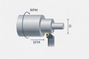
- RPM (Revolutions Per Minute): Describes the number of rotations the spindle makes per minute, which is a fixed angular velocity.
- SFM: Describes the actual physical distance traveled by the cutting edge.
- The Diameter Relationship: At the same RPM, a workpiece or tool with a larger diameter will have a higher SFM at its edge. This means that when machining large-diameter parts, the RPM must be significantly reduced; otherwise, the cutting edge may burn instantly due to excessive linear speed.
Parameter Conversion Between SFM and RPM
The numerical relationship between these two parameters is governed by the tool diameter (D) and the mathematical constant π:
- Converting RPM to SFM: Since the distance traveled per revolution is equal to the circumference (π × D), the linear velocity is found by multiplying the RPM by the circumference. Because the diameter (D) is typically measured in inches, we divide by 12 to convert the value into feet:
SFM = (RPM × π × D) / 12 - Converting SFM to RPM: This is the most frequent calculation used on the shop floor. To maintain a specific SFM, the RPM must be adjusted inversely to the diameter. Engineers use the following simplified formula for quick calculations:
RPM ≈ (SFM × 3.82) / D
(Where 3.82 is the constant derived from the ratio 12 / π.)
Factors Affecting SFM
Before setting the SFM, multiple variables within the machining system must be comprehensively evaluated, as these factors define the upper limits of safe cutting speeds:
- Workpiece Material: This is the decisive factor. For instance, aluminum alloys allow for extremely high linear speeds, whereas titanium alloys—due to their high hardness and poor thermal conductivity—require a significant reduction in SFM.
- Tool Material and Coating: Carbide tools offer heat resistance far superior to High-Speed Steel (HSS). Furthermore, high-performance coatings (such as AlTiN) provide a thermal barrier, further pushing the limits of cutting speed.
- Coolant Application: Effective cooling and lubrication can rapidly dissipate heat from the cutting zone, allowing the machine to operate stably at higher SFM levels.
- Machine System Rigidity: If the machine, fixture, or tool holder lacks stability, high-speed machining can easily induce resonance. To ensure dimensional precision, it is often necessary to proactively limit the SFM to avoid unstable vibration zones.
Common Errors
When setting machining parameters, empiricism often leads to incorrect SFM choices, which in turn damages machining quality and tool life. Below are several common pitfalls in actual operations:
- Maintaining a Fixed RPM During Facing: As the tool moves toward the center of the part, the effective diameter approaches zero, and the SFM decreases accordingly. This leads to poor surface roughness at the center or the generation of BUE. It is recommended to use the G96 (Constant Surface Speed) command, allowing the machine to automatically compensate RPM as the diameter decreases.
- Blindly Following Outdated Reference Manuals: Many manuals used in factories were written decades ago, whereas the physical performance of modern high-performance coatings (like AlTiN) far exceeds traditional data. It is suggested to always prioritize the latest technical data sheets from your current tool supplier and fine-tune based on machine rigidity.
- Ignoring Material Heat Sensitivity: For materials with poor thermal conductivity like stainless steel, blindly increasing SFM for efficiency will cause heat to accumulate instantly at the tool tip, leading to edge chipping.
How to Adjust SFM Values for Different Materials?
Different metals react differently to frictional heat based on their molecular structure and physical properties. When setting the SFM, it is essential to adjust the values according to the specific attributes of the material:
Common Material SFM Reference Table
| Material Category | Recommended SFM Range | Machining Advice |
| Aluminum Alloys | 600 – 1500+ | Excellent thermal conductivity. High speeds yield superior finish and prevent chip welding. |
| Carbon Steel | 300 – 800 | The most common material. Balance heat generation and tool wear based on carbon content. |
| Alloy Steel | 250 – 600 | High strength and toughness. Use moderate speeds to balance efficiency and tool life. |
| Stainless Steel | 150 – 350 | Prone to work hardening and poor heat dissipation. Strict speed control is required. |
| Cast Iron | 250 – 500 | Abrasive structure. Adjust based on graphite type; ductile iron usually requires lower speeds. |
| Titanium Alloys | 80 – 150 | High risk of thermal failure. Requires low speeds combined with high-pressure coolant. |
| High-Temp Alloys | 50 – 120 | Retains strength at extreme heat. High tool wear; requires very low speeds and advanced coatings. |
| Brass and Bronze | 400 – 1000 | Easy to machine. Allows for higher speeds, though some alloys may be abrasive to tools. |
Aluminum Alloys
Aluminum offers excellent machinability and thermal conductivity. High linear speeds not only boost production efficiency but also effectively prevent material from adhering to the cutting edge—known as Built-Up Edge—resulting in a mirror-like surface finish.
Carbon Steel
As the most widely used machining material, carbon steel has a broad SFM range. The carbon content is the primary guide: lower carbon steels allow for higher speeds, while higher carbon or tempered steels require lower values to balance heat and physical tool wear.
Stainless Steel
Stainless steel is characterized by significant work-hardening properties. Due to its poor thermal conductivity, cutting heat accumulates rapidly at the tool tip. If the SFM is too high, the cutting edge will quickly soften or even fracture under the intense temperature.
Cast Iron
The internal abrasive particles and the morphology of graphite (flaked or nodular) significantly impact cutting resistance. SFM settings must be handled with care; for instance, ductile iron is tougher than gray iron and generally requires a lower cutting speed.
Titanium and Nickel-Based Alloys
Often referred to as superalloys, these materials generate extreme temperatures at the point of cut. To maintain a controllable machining process, speed must be sacrificed, keeping the SFM within a very low range to ensure tool integrity.
Brass and Bronze
These materials are generally known for their excellent machinability. High linear speeds can be applied to achieve high production rates and a clean surface finish. However, it is important to monitor tool wear when working with specific bronze alloys that contain abrasive elements, as they can be more taxing on the cutting edge than standard free-cutting brass.
Conclusion
SFM is more than just a speed parameter. It reflects how well the tool, material, and cutting conditions are matched. Understanding and setting SFM correctly can help improve surface finish and tool life while making the overall machining process more stable and efficient.
FAQ
Is a Higher SFM Always Better?
No. A higher SFM can improve machining efficiency and, in some cases, surface finish, but only if it stays within a suitable range. If SFM is too high, tool wear may increase quickly and cutting heat may become more concentrated. If SFM is too low, built-up edge, unstable cutting, and poor surface finish are more likely to occur. The right SFM is usually the one that creates a good balance between tool life, part quality, and machining efficiency.
What Tools Can Be Used to Calculate SFM?
In actual machining, there are four common types of tools used to calculate SFM. The first is an online SFM calculator, which allows users to enter tool diameter and spindle speed, or start with a recommended SFM and calculate RPM. The second is cutting data charts or digital catalogs provided by tool manufacturers, which list recommended SFM, feed, and speed ranges for different materials. The third is machining mobile apps, which often include quick conversions for SFM, RPM, feed rate, and drilling data. The fourth is the built-in calculation functions found in some CNC programming software or CAM systems, which help define cutting speed and spindle speed during programming. In practice, these tools should be used as a starting point, and the final settings should still be adjusted according to the material, tool, and actual cutting conditions.
What Is a Good SFM for Steel?
There is no single SFM value that works for all steels. The right range depends on the steel grade, hardness, tool material, coating, and coolant condition. In general, low-carbon steel often allows a higher SFM, while alloy steel or hardened steel usually requires a more conservative range. In actual machining, the safest approach is to start with the tool supplier’s recommended data and then fine-tune the speed based on tool wear, surface finish, and cutting stability.