
When the part design includes inclined surfaces, chamfers, or transitions that are not aligned with the main axes, angle milling becomes a practical way to machine them in one setup. A clear understanding of how the cutting angle is established—by tool orientation, workpiece tilting, or special cutters—directly translates into better accuracy and fewer re-clampings. The sections below define angle milling and walk through its key use cases and common process configurations.
What is Angle Milling?
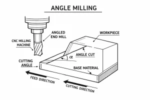
Angle milling refers to the process of machining specific geometric features on a workpiece by adjusting the relative angle between the rotation centerline of the cutting tool and the workpiece surface. During the process, the tool edge moves in a vector direction that is non-perpendicular or non-parallel to the workpiece. Depending on requirements, this is achieved by changing the mounting angle of the workpiece, tilting the machine spindle head, or using angled milling cutters with a conical geometry.
What is the Purpose of Angle Milling?
In engineering design, angle milling is used to achieve specific mechanical functions and ensure proper assembly. Its core purposes include:
-
Precision Fit and Smooth Motion: It is essential for creating guiding surfaces, such as dovetail slots on machine tool ways. These angled features allow moving parts to slide accurately and remain stable during operation.
-
Improving Structural Durability: Sharp right-angle corners are prone to stress concentration, which can lead to cracks. By milling chamfers (beveled edges), we eliminate these weak points, reducing the risk of fatigue failure and extending the part’s life.
-
Specialized Tool Manufacturing: Many rotary tools, such as reamers and slot drills, require complex helical flutes and cutting angles. Angle milling is the primary process used to create these precise tool geometries.
-
Ensuring Smooth Mold Release: In mold making, a slight angle called a “draft angle” is milled into the cavity walls. This reduces friction during the de-molding process, ensuring that parts can be ejected easily without getting stuck or damaged.
Successful angle milling requires a structured workflow to ensure geometric accuracy. The process typically follows these key stages:
Process Strategy
First, analyze the part drawing to locate the angular feature relative to the design datum. Technicians must decide on the best approach: tilting the workpiece, tilting the milling head, or using a pre-shaped angle cutter. This decision is vital as it affects how the fixture is designed and how cutting forces will be managed.
Workpiece Setup
Mount the workpiece securely in a vise or specialized fixture. If the strategy involves tilting the part, you will need auxiliary tools like angle plates, sine tables, or universal tilting vises. It is essential to keep all support surfaces clean, as even tiny debris can cause significant angular errors.
Alignment & Calibration
Accuracy depends on careful calibration. Operators typically use a dial indicator to sweep along the intended machining path. For high-precision requirements, a sine bar and gauge blocks are used to achieve micron-level positioning. If you are tilting the machine’s spindle head, ensure the housing is locked tight and re-verify its stability before starting.
Parameter Configuration
Perform tool setting to sync the tool with the workpiece coordinate system, ensuring radius and length offsets are accurately entered. Set the cutting speed and feed rate based on the material. Since angle milling creates side pressure (lateral forces), optimize the feed per tooth to prevent the tool from bending or pushing away from the part.
Machining & Control
To prevent the part from deforming under pressure, a layered machining approach is best. Start with roughing passes to remove most of the material. Before the final finishing pass, re-check the angle—this helps compensate for any tiny shifts caused by the release of internal material stress.
Quality Assessment
Before removing the workpiece from the machine, verify the dimensions using a universal protractor, precision gauges, or an on-machine probe. It is much easier to make adjustments now than after the part has been unloaded. Only remove the workpiece once the angle and position are fully confirmed.
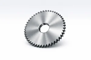
Types of Angle Milling Cutters
Angle milling cutters are rotary tools specifically designed for machining angular features, with cutting edges distributed on conical or tilted lateral surfaces.
Single Angle Milling Cutters
The cutting edges of a single angle cutter are distributed on a single tilted lateral surface, and its cross-section is typically a right-angled triangle. Because the cutting force is distributed in one direction, this tool provides good lateral stability when machining single-sided slopes or dovetail sidewalls. Standard angles include 30°, 45°, and 60°.
Double Angle Milling Cutters
Double angle cutters have cutting edges on two tilted lateral surfaces that meet at a point on the circumference, forming a V-shaped profile. The advantage of this design is that it can machine two angled surfaces simultaneously in a single pass, ensuring symmetry and positional consistency. They are commonly used for V-guides and thread profiles.
Suitable Materials for Angle Milling
Angle milling is applicable to most metals and non-metals used in industrial manufacturing. Material properties dictate the configuration of process parameters:
- Ferrous Metals: Including carbon steel, alloy steel, and stainless steel. These materials involve high cutting forces and heat; therefore, focus must be placed on coolant chemistry and flow rate.
- Non-Ferrous Metals: Such as aluminum, copper, and their alloys. These offer high machining efficiency, but anti-adhesive tool coatings should be selected to prevent material build-up from affecting angular precision.
- Cast Iron: Due to its excellent vibration-damping characteristics, it is often used for machine tool base guides. Specialized chip evacuation systems are needed to handle brittle chips.
- High-Performance Materials: Including titanium alloys, superalloys, and composites. Often found in aerospace applications, these require high tool hardness and wear resistance.
Advantages of Angle Milling
Compared to traditional layer-by-layer approximation machining, angle milling offers significant technical advantages for non-orthogonal surfaces:
- Expanded Machining Flexibility: Enables standard three-axis machines to process complex tilted features, reducing reliance on expensive five-axis equipment.
- Consistent Surface Finish: The single-pass cutting mode avoids the “staircase effect” produced by ball-nose end mill step-over scanning, resulting in a flatter and more uniform surface texture.
- Production Efficiency Optimization: Specialized shaped tools or one-time process setups significantly reduce non-cutting travel and programming complexity.
- Controllable Dimensional Accuracy: Provided the system rigidity is sufficient, it maintains high angular repeatability, benefiting tolerance control in mass production.
Limitations of Angle Milling
The process is constrained by physical rigidity and economic costs in practical operations:
- High Setup and Calibration Time: Angular alignment and precision positioning are relatively time-consuming and require high skill levels in precision metrology.
- Rigidity Challenges: Non-orthogonal mounting or excessively extended spindle heads can significantly reduce the dynamic rigidity of the process system, inducing vibrations or “chatter.”
- Complex Cutting Force Vectors: The large lateral force components generated during machining can cause slight workpiece displacement or tilting if the clamping force is insufficient.
- Tool Inventory Management: Due to the wide variety of angles required, companies must maintain a large inventory of cutters, and custom angles often involve high procurement costs.
Applications and Case Studies
Angle milling is widely used in industries pursuing precision assembly and specific mechanical performance.
- Machine Tool Manufacturing: Milling V-guides and dovetail slots on machine beds and tables is a core step in ensuring motion accuracy.
- Mold Making: Machining angled pin tracks, slider mating surfaces, and critical angular cavities in injection and die-casting molds.
- Aerospace: Machining angular stiffeners, brackets, and skin interfaces with specific aerodynamic features on aircraft structural components.
- Power Machinery: Used for machining angled valve seats in internal combustion engines, hydraulic cone valve sealing surfaces, and angular ports for pump components.
Best Practices for Angle Milling
To ensure machining accuracy and extend tool life, the following technical guidelines should be followed:
- Maximize System Rigidity: Shorten the extension length of tools and fixtures, and ensure the cutting force acts as close to the support point as possible to suppress lateral bending.
- Static and Dynamic Alignment: Re-verify with a dial indicator over the full length of the travel to ensure the workpiece tilt is within tolerance.
- Optimize Milling Strategy: Use climb milling when the setup is stable to improve surface finish; consider conventional milling if rigidity is low to reduce impact.
- High-Efficiency Fluid Lubrication: Ensure coolant is directed precisely at the cutting zone to reduce heat and flush away chips to prevent secondary cutting.
Angle Milling vs. Traditional Milling
Traditional milling focuses on linear cutting within an orthogonal coordinate system, featuring standardized setups and excellent rigidity. In contrast, angle milling introduces non-orthogonal variables, essentially achieving complex spatial features through geometric displacement on a stable mechanical platform. This requires technicians to possess strong trigonometric calculation skills and a deep understanding of cutting force vector decomposition to balance flexibility with machining precision.
Conclusion
Angle milling is an essential specialized technique in modern machining, providing efficient and precise solutions for manufacturing complex geometric surfaces. Despite technical challenges in setup and rigidity control, its technical and economic advantages in functional surface processing make it a cornerstone of the precision manufacturing chain. Mastering the in-depth application of this process is fundamental to achieving high-quality component production and optimized assembly performance.
Request a comprehensive technical proposal and tool-setting manual for high-precision angle milling. Submit your workpiece drawings to receive customized cutting parameter recommendations for difficult-to-machine materials