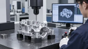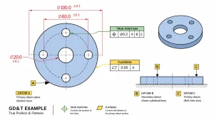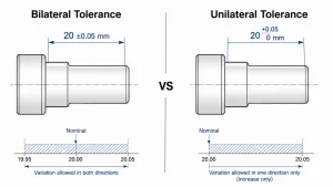

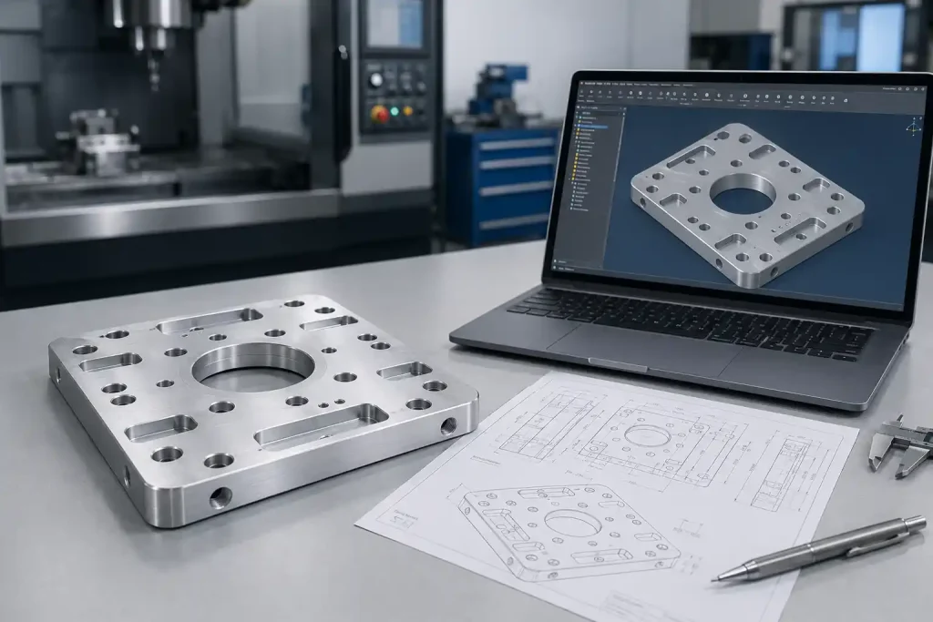

Antes do início de um projeto de maquinagem CNC, o fabricante necessita normalmente de rever os ficheiros CAD, em vez de passar diretamente à produção. Estes ficheiros são normalmente criados através de conceção assistida por computadorque define a geometria da peça antes de ser transferida para a programação e fabrico CAM. Os modelos 3D são utilizados para verificar a geometria da peça, enquanto os desenhos de engenharia 2D especificam tolerâncias, roscas, acabamento de superfície, materiais e requisitos de pós-processamento. Se o formato do ficheiro não for adequado ou se os detalhes do modelo não forem claros, isso pode afetar a cotação, as revisões de engenharia e a programação CAM.
Este artigo descreve os formatos de ficheiros CAD comuns utilizados na maquinagem CNC, os seus cenários de melhor utilização e as verificações de conceção e preparação que deve efetuar antes de submeter os seus ficheiros para fabrico.
Porque é que a precisão do CAD afecta a maquinagem
A maquinagem CNC é um processo orientado por dados em que o software CAM lê diretamente os dados do modelo para gerar percursos de ferramentas. Quaisquer discrepâncias no modelo CAD são amplificadas durante a produção e afectam diretamente a qualidade da peça final:
- Distorção do percurso da ferramenta: Se um modelo contiver superfícies quebradas ou geometrias que se intersectam, o software CAM pode não conseguir identificar os limites, levando a um corte a ar ou a uma goivagem acidental.
- Tolerância e desalinhamento de ajuste: Embora os modelos 3D sejam precisos, não conseguem transmitir totalmente os requisitos de ajuste complexos. Se os desenhos 2D não tiverem informações ou estiverem em contradição com o modelo, o fabricante terá dificuldade em cumprir os requisitos funcionais.
- Capacidade de fabrico físico: Um modelo CAD preciso permite a avaliação da espessura da parede e dos raios de filete. Isto ajuda a identificar riscos - como a interferência da ferramenta - durante a fase de programação, evitando problemas que só poderiam ser descobertos durante o processo de corte efetivo.
Formatos de ficheiros CAD comuns
A escolha de formatos de ficheiro padrão da indústria é o primeiro passo para garantir que os dados são transferidos de forma eficiente e sem perdas.
- STEP (.stp / .step): O formato neutro padrão da indústria. Regista com precisão a geometria e a topologia de um sólido, tornando-o o formato preferido para maquinação CNC e programação CAM devido à sua compatibilidade superior.
- IGES (.igs): Um formato essencialmente centrado na transferência de geometria de superfície. Embora a sua robustez de dados seja ligeiramente inferior à do STEP para modelos sólidos complexos, continua a ser utilizado em colaborações que envolvem equipamentos mais antigos.
- Formatos nativos (.sldprt / .prt / .CATPart): Ficheiros nativos de software como o SolidWorks, NX ou CATIA. Estes formatos retêm a árvore de caraterísticas, permitindo aos fabricantes efetuar as optimizações de design necessárias, desde que as versões de software sejam compatíveis.
- Evitar STL (.stl): O STL é um formato baseado em malha composto por numerosas facetas triangulares. Não pode fornecer os limites matemáticos exactos necessários para a maquinagem CNC e é geralmente considerado como dados não maquináveis para componentes metálicos de alta precisão.
Dicas de otimização de design CAD
Durante a fase de conceção do produto, a antecipação das caraterísticas físicas da maquinagem CNC e a modelação em conformidade podem reduzir significativamente os riscos e as dificuldades de fabrico.
Otimização da geometria
Evitar cantos internos afiados. Uma vez que as ferramentas de corte CNC são cilíndricas, os cantos internos afiados não podem ser cortados diretamente. Deve incorporar filetes no seu modelo CAD sempre que possível, assegurando que o raio do filete é igual ou superior ao raio da ferramenta pretendida.
Espessura da parede e controlo estrutural
Evitar projectos com paredes demasiado finas. Recomenda-se geralmente manter uma espessura de parede de pelo menos 0,8 mm - 1,0 mm para evitar ressonâncias ou deformações durante o corte a alta velocidade, o que poderia comprometer a qualidade da superfície.
Conceção normalizada
Sempre que possível, faça corresponder os diâmetros dos furos a tamanhos de brocas ou fresas de topo padrão para reduzir os custos associados a ferramentas não padronizadas. Além disso, defina pontos de referência de medição claros no modelo CAD para facilitar a montagem e a inspeção de qualidade.
Lista de verificação do ficheiro CAD
Antes de enviar os seus ficheiros CAD para o seu parceiro de fabrico, considere realizar esta auto-verificação para garantir que os seus dados podem ser interpretados com precisão pelo sistema de produção:
- Integridade geométrica: Confirme que o modelo é um sólido fechado, sem superfícies em falta ou limites desligados.
- Unidades: Especificar claramente as unidades de desenho (milímetros ou polegadas) para evitar erros de escala causados por má interpretação.
- Sistema de coordenadas: Definir um Sistema de Coordenadas de Trabalho (WCS) consistente para garantir que a orientação do modelo corresponde à lógica de fabrico.
- Desenhos associados: Se existirem tolerâncias críticas, especificações de rosca ou requisitos de tratamento de superfície, incluiu um desenho de engenharia em PDF 2D?
- Simplificar a redundância: Remova os componentes de montagem desnecessários (como parafusos ou anilhas) ou a geometria de referência para manter o ficheiro limpo.
Conclusão
Os ficheiros CAD claros reduzem a comunicação durante a orçamentação e as revisões de engenharia e ajudam a equipa de produção a efetuar uma programação e preparação CAM precisas. Para a maioria dos projectos de maquinagem CNC, recomenda-se que seja fornecido um modelo 3D em formato STEP ou STP e um desenho 2D em PDF que inclua todas as tolerâncias críticas, roscas, acabamentos de superfície e requisitos de material. Quanto mais clara for a preparação do seu ficheiro, mais eficazmente o seu projeto passará pela avaliação do fabrico, programação e inspeção de qualidade.