
五轴数控系统设计:不仅仅是增加轴数
你有一个复杂的零件。CAD 模型看起来很棒——表面光滑,间隙小,到处都是倒扣。你把它送到车间,心想:“他们有一台五轴机床,什么都能处理。”
然后电话来了:“我们需要修改设计。刀具够不到这些区域,工件夹持也会有问题。”
听起来很熟悉?
五轴数控加工功能强大,毋庸置疑。但仅仅因为一台机床能够倾斜、旋转并从五个方向切割,并不意味着您的设计就能够轻松制造,甚至可能直接制造。
事实上,五轴加工需要更智能的设计,而不仅仅是更精巧的几何形状。
想要释放五轴加工的真正潜力——更短的交付周期、更优的表面光洁度、更少的设置——一切从设计阶段开始。
而许多项目往往在这一阶段偏离正轨。
本指南并非仅仅是一份设计规则清单。它源自真实的机加工车间,由亲眼见证过哪些方法有效、哪些方法失败的工程师们提供指导。
无论您设计的是涡轮叶片、骨科植入物,还是复杂的外壳,本指南中的见解都旨在帮助您一次性成功。
让我们来看看好的 5 轴零件设计到底是什么样的,以及即使是经验丰富的设计师也会犯的常见错误。
良好的 5 轴设计在机器启动之前就开始了
💡 伟大的设计应该让机械师的工作更轻松,而不是更艰难。
关于五轴数控加工最大的误解之一是,它默认解决了所有设计难题。设计师通常认为,由于可以从几乎任何角度自由加工零件,他们可以对复杂的几何形状进行建模,而无需过多考虑可制造性。
但在实际应用中,尤其是在航空航天、汽车和医疗行业,粗心的五轴零件设计可能会:
- 复杂的刀具路径编程
- 增加加工时间
- 表面光洁度较差
常见痛点:设计在模拟中看起来不错,但由于工具访问或设置限制,在实践中失败。
✅ 尽早考虑:
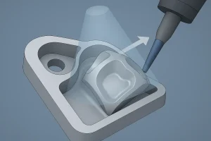
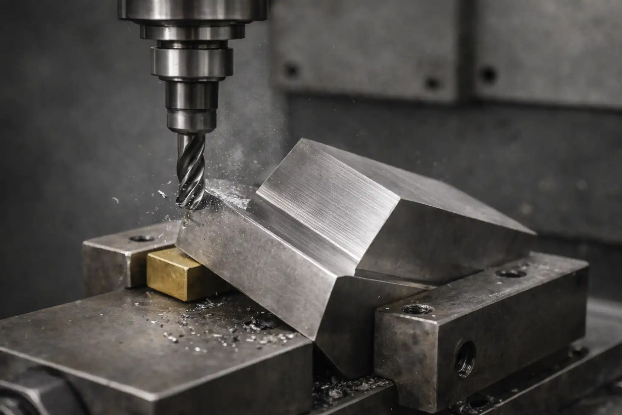
五轴加工中凹陷特征的刀具访问评估
- 该工具能否实现每个关键功能?
- 您是否依赖可能偏转的过长工具?
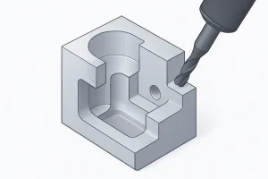
说明了 5 轴 CNC 设计中切削刀具和零件特征之间的间隙的重要性。
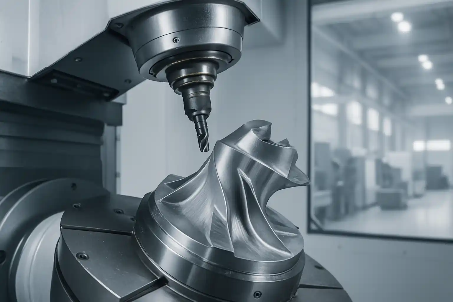
- 所有表面是否与机器的旋转轴对齐?
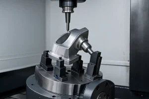
演示如何在 5 轴加工中固定零件以实现多面访问。
注意壁厚和工具啮合
🛠 墙体强度不仅仅是一个结构问题,也是一个加工问题。
薄壁和深槽是导致刀具变形和颤动的根源。即使是强度高的材料,在切削力的作用下也会弯曲。这会导致:
- 振动
- 表面光洁度问题
- 尺寸精度差
最佳实践:
- 壁厚均匀:力求横截面一致
- 使用加强筋:特别是在局部较薄区域周围
- 注意 L:D 比率:尽可能保持在 5:1 以下
- 添加充足的圆角: 1-2 毫米内半径可防止刀具断裂
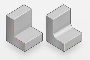
尖锐内角与 5 轴刀具访问优化圆角半径的比较。
- 优化刀具啮合:避免急剧下陷或无支撑的侧壁
影响五轴加工成功的常见陷阱
❌ 这些错误比你想象的更常见,而且比看起来的更昂贵。
要避免的主要陷阱:
- 过于复杂的几何形状毫无价值
- 无需夹紧或基准面来固定
- 尖锐的内角需要使用易碎工具
- 与旋转轴对准不良
- 无支撑的悬垂结构会增加振动风险
真实案例:
一家医疗器械公司设计了一个带有深槽和尖角的零件。它通过了虚拟测试,但由于刀具颤动,在生产中屡屡失败。通过添加圆角并将特征旋转 15°,机械师将生产周期缩短了 30%。
为什么早期合作比事后纠正错误更有效
🤝 大多数重新设计都是在零件失效后进行的。让我们把话题提前。
早期的 DFM 评审可以帮助您:
- 在编程开始之前捕获无法访问的功能
- 通过简单的圆角调整节省数小时的 CAM 时间
- 提高夹具稳定性和零件方向
- 在工程和制造团队之间建立信任
💡 今天进行 1 毫米的圆角半径调整可以节省数小时乃至数千美元的返工成本。
最后的想法:设计时要考虑最终结果
五轴数控加工具备灵活性、精度和速度——但前提是设计能够支持该工艺。
好的设计并非关乎复杂性,而是关乎清晰度、可访问性和协作性。
✅ 像机械师一样思考:
- 切割机将如何移动?
- 固定装置位于哪里?
- 当部件变热时会发生什么?
当您将 CAD 策略与制造现实相结合时,您就可以避免错误并释放真正的价值。
与了解 5 轴加工的团队合作
在明和,我们已经帮助数百名工程师优化了他们的 5 轴设计——从航空支架到复杂的模具镶件。
我们提供:
- 免费设计制造 (DFM) 评审
- 快速原型和高精度生产
- 诚实的反馈和实际工具建议