

Before a part enters machining, it usually exists first as a digital drawing or 3D model. CAD, or Computer-Aided Design, is the tool used to create this digital design. It helps engineers define the part’s shape, dimensions, structural features, and manufacturing requirements before production begins.
This article explains what CAD is, the common types of CAD, its main applications, and why CAD files can affect CNC machining and manufacturing workflows.
What Is CAD?
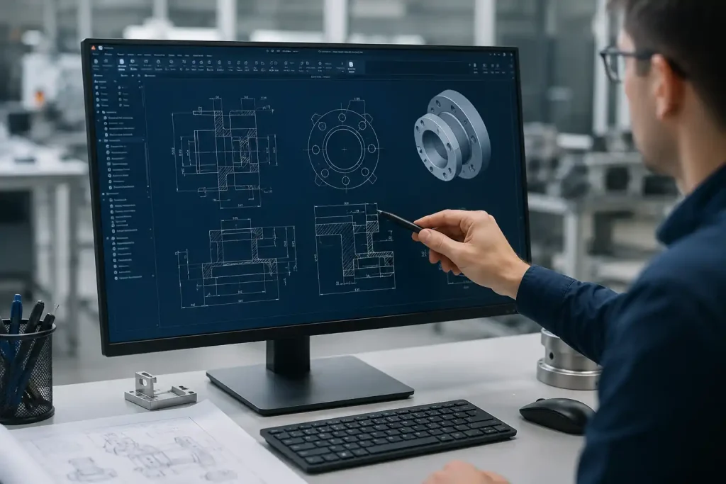
CAD (Computer-Aided Design) is a common technology used to create virtual prototypes of products. In production workflows, the CAD model serves as a technical reference, containing the geometric data that CNC machines require for operation, such as hole locations, chamfers, and wall thickness parameters.
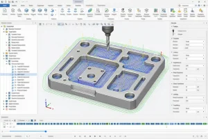
Using CAD technology allows teams to validate designs before committing to physical production. By identifying structural interference and optimizing geometry in a virtual environment, companies can reduce trial-and-error costs, minimize material waste, and ensure that designs are well-suited for the manufacturing process.
Brief History of CAD
The development of CAD technology began in the 1960s. Initially, it served merely as a digital aid for manual drafting, used primarily for drawing simple geometric lines. As the processing power of computer hardware rapidly advanced, CAD technology made the leap from 2D sketching to 3D solid modeling in the 1980s. Starting in the 1990s, the emergence of parametric design and integrated manufacturing systems fundamentally transformed the logic of production, allowing engineers to automatically update entire design models by changing parameters. Today, CAD has evolved from a simple drafting tool into a comprehensive digital platform that integrates simulation analysis, mold development, and intelligent manufacturing planning, becoming the cornerstone of modern industrial innovation.
Differences Between CAD and Traditional Drafting
Compared to traditional manual drafting, CAD significantly improves efficiency through digital methods:
Design Representation
Traditional drafting relies on 2D drawings and manual spatial visualization. CAD creates 3D solid models that can be viewed from any angle, making the design intent intuitive and clear.
Modification and Iteration
In traditional drafting, modifications often require redrawing. CAD utilizes parametric design, allowing engineers to update models and drawings automatically by changing parameters, significantly reducing repetitive work.
Data Accuracy
Traditional drawings are prone to scaling and annotation errors. CAD uses precise numerical data, ensuring geometric accuracy and allowing for direct integration into production processes.
What Are the Types of CAD?
Depending on the complexity of the part and specific manufacturing requirements, engineers typically utilize three types of CAD:
2D CAD
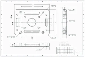
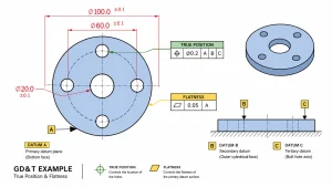
This is a digital method of creating traditional engineering drawings. It uses two-dimensional views to detail profiles, dimensions, and manufacturing notes. In CNC machining, 2D drawings serve as an important supplement to 3D models, especially when communicating Geometric Dimensioning and Tolerancing (GD&T), surface finish requirements, and assembly instructions that may be overlooked in 3D modeling.
3D Solid CAD
This is a common method used in CNC machining. A solid model represents a closed geometric volume containing full mass and structural properties. Because the system recognizes the part as a physical object, CAM software can automatically identify features like pockets, faces, and bores to generate efficient toolpaths for mechanical and structural components.
3D Surface CAD
For parts with complex, organic shapes—such as automotive body panels or products with specific streamlined features—engineers use surface modeling. Unlike solid modeling, this approach focuses on defining the outer skin or shell of a part. In multi-axis CNC machining, surface models guide tools along complex, flowing contours to achieve high-precision results for geometries that are difficult to define with solid modeling.
Common CAD Applications
CAD technology serves as the digital core of manufacturing, covering the entire process from design to production across various industries:
Machining
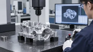
In the design of parts and tooling, CAD is used to define geometric shapes and tolerance standards. By inputting design data directly from the model into CAM systems, it generates toolpaths, enabling standardized processing for milling, turning, and drilling.
Transportation
This industry utilizes surface modeling to handle exterior shells and internal structures. CAD is used to define complex geometric profiles and perform virtual assembly verification to optimize part fit and assembly processes.
Aerospace
For high-performance components, CAD is used to develop complex aerodynamic surfaces. By combining models with analysis tools, engineers optimize material distribution and wall thickness to meet structural stability requirements under extreme operating conditions.
Consumer Electronics
In electronic product development, CAD is used to build internal mounting points, cooling structures, and housing profiles. Parametric modeling allows engineers to quickly adjust part parameters to meet the technical requirements of mold manufacturing or CNC machining.
CAD Advantages
CAD technology optimizes product development through digital methods, providing practical value throughout the manufacturing process:
Improved Design Accuracy
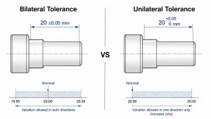
CAD provides a high-precision modeling environment that clearly defines part dimensions, tolerances, and geometry. This approach eliminates the interpretation errors associated with traditional drawings, ensuring consistency throughout the manufacturing stage.
Faster Development Cycles
With parametric modeling, engineers can quickly adjust designs when specifications change without starting from scratch. This flexibility shortens the time from concept to final design, helping businesses respond more efficiently to market demands.
Reduced Manufacturing Costs
By performing virtual assemblies on a computer, structural issues between parts can be identified in advance. This pre-validation reduces the error rate during prototype production and avoids the extra investment required for mold rework.
Simplified Production Integration
The direct link between CAD and CAM systems is key to achieving automation. Design data can be converted directly into operational instructions for CNC machines, reducing intermediate steps and ensuring a smoother transition from design to production.
Commonly Used CAD Software Tools
Depending on the depth of application and specific industry requirements, the following are the mainstream CAD software tools used in manufacturing:
SolidWorks
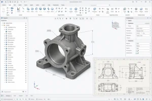
Widely used in mechanical design and product development. With its user-friendly interface and powerful parametric modeling capabilities, it is ideal for structural design, assembly verification, and engineering drawing generation for small to medium-sized parts, making it a top choice for standardized manufacturing.
AutoCAD
The industry standard in the CAD field, primarily used for 2D drafting and layout design. While its 3D modeling capabilities are relatively limited, it remains highly efficient and irreplaceable for creating 2D part drawings, circuit layouts, and factory floor plans.
UG NX
A comprehensive platform designed for complex industrial engineering, widely used in high-end manufacturing sectors like automotive and aerospace. It excels at handling extremely complex surface modeling and features deeply integrated CAM toolpath planning, making it suitable for high-precision, large-scale manufacturing processes.
Pro/E (Creo)
Renowned for its powerful parametric modeling, it is well-suited for the iterative development of complex mechanical structures. It ensures stability in design management by maintaining associative design intent, meaning that when part dimensions are changed, associated assemblies and engineering drawings are updated automatically.
Essential Skills and Certifications for CAD Professionals
To succeed in a CAD career, one must balance software proficiency with a solid grasp of manufacturing standards and processes. Here are the detailed suggestions:
Is CAD difficult to learn?
Generally, the basics are quite accessible, but mastering the software takes time and project-based practice. The entry-level phase focuses on spatial reasoning and command familiarity, while the advanced level requires a deep understanding of manufacturing processes, material science, and engineering standards. With consistent practice on real-world projects, CAD will become a powerful and intuitive tool in your professional toolkit.
Technical Skills
Technical mastery is the foundation for ensuring product quality and manufacturability.
- Software Proficiency: Mastery of industry-standard tools (e.g., SolidWorks, UG NX, or Creo) for efficient 3D modeling, assembly design, and parametric iterations.
- Drafting & Standards: Ability to interpret complex blueprints and produce engineering drawings that strictly comply with industry standards, utilizing GD&T for precision.
- Manufacturing Logic (DFM): Solid understanding of machining processes (milling, turning, casting) to ensure designs are manufacturable and cost-effective.
- Data Integration: Competence in data conversion (STEP/IGES) to ensure seamless workflows between CAD and CAM systems.
Recommended Certifications
Certifications serve as valuable endorsements for employment, and it is recommended to choose them based on your specific career goals.
- Manufacturer Certifications (Industry Standard): The most recognized proof of software mastery.
- SolidWorks: CSWP (Professional level, the industry gold standard for job seekers).
- Siemens NX: Highly valued in high-end sectors like aerospace and automotive.
- Autodesk (ACP): A widely recognized benchmark for 2D/3D design proficiency.
- Vocational Qualifications: Often used as supplementary credentials for entry-level positions in state-owned enterprises or large-scale projects.
Conclusion
CAD technology serves as the foundation of modern manufacturing, linking product design with actual production. Beyond improving drafting efficiency, it ensures precision and feasibility throughout the manufacturing process. For professionals, mastering CAD, combined with a solid understanding of manufacturing processes, is essential for efficiently transforming creative concepts into physical products and remains a key factor for long-term career growth.