
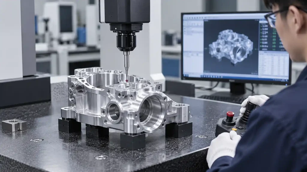
The quality of a product depends largely on whether effective quality checks are performed throughout the manufacturing process. This article explains the CNC quality inspection process, common inspection methods and tools, and the steps used to verify the quality of CNC-machined parts.
What Is CNC Quality Inspection?
CNC quality inspection is the process of using inspection tools and methods to determine whether a finished machined part meets the engineering drawing and customer requirements. Typical inspection characteristics include dimensional tolerances, geometric accuracy, surface roughness, and material properties.
Quality inspection is applied throughout the 数控加工 process to verify that finished parts meet drawing and customer requirements. It may also be referred to as quality testing, product inspection, quality verification, or quality checking.
Why Is CNC Quality Inspection Important?
Quality inspection is an essential part of manufacturing because it verifies that CNC-machined parts meet the specified technical requirements. It helps maintain dimensional consistency, improve acceptance rates, and prevent quality problems from continuing through the production process.
For example, during 数控车削 of a shaft, first-article inspection may show that the diameter is already approaching the upper tolerance limit. The operator can then adjust the tool offset before continuing production, preventing the remaining parts from becoming oversized. If the problem is discovered only after the entire batch has been completed, it may result in large-scale rework or scrapped parts.
Effective quality inspection reduces manufacturing risks, improves consistency, and strengthens customer confidence. It also supports more reliable quality standards throughout the CNC machining industry.
What Is the Difference Between Quality Assurance, Quality Control, and Quality Inspection?
Quality assurance, quality control, and quality inspection are closely connected, but they perform different functions within a manufacturing quality system.
Quality assurance (QA) focuses on establishing and maintaining a quality management system. It ensures that manufacturing activities follow clearly defined standards, procedures, responsibilities, and documentation requirements.
Quality control (QC) applies these requirements to specific production activities. It includes first-article inspection, in-process inspection, tool-offset adjustment, process monitoring, and corrective action.
Quality inspection uses tools such as calipers, micrometers, and coordinate measuring machines to evaluate dimensions, geometric tolerances, surface quality, and other specified characteristics. The results are compared with engineering drawings, standards, or customer requirements to determine whether the part is acceptable.
In simple terms:
- Quality assurance controls the overall system.
- Quality control manages the production process.
- Quality inspection measures and verifies conformance.
Common Quality Inspection Tools for Machined Parts
Quality inspection tools should be selected based on dimensional tolerances, geometric features, material properties, and potential defect types. Standard dimensions can often be checked with manual measuring tools, while complex profiles, tight geometric tolerances, and internal defects require specialized inspection equipment.
Shop-Floor Measuring Tools and Gauges
Shop-floor measuring tools and dedicated gauges are easy to use and provide fast results. They are commonly used for first-article inspection, in-process checks, and high-volume production inspection.
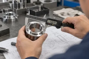
- Calipers: Measure length, thickness, inside and outside diameters, and depth for general-tolerance applications.
- Micrometers: Measure precise outside diameters, inside diameters, and thicknesses with greater accuracy than standard calipers.
- Dial indicators and test indicators: Check dimensional variation, runout, flatness, and parallelism.
- Plug, ring, and thread gauges: Use go/no-go inspection to quickly determine whether holes, shafts, and threads are within tolerance.
The resolution and measuring range of each tool should match the specified tolerance. All measuring tools should also be calibrated at defined intervals.
Coordinate Measuring and Optical Inspection Equipment
Complex or high-precision machined parts often require coordinate measuring or optical inspection equipment. These systems can measure dimensions, profiles, and geometric relationships that are difficult to verify with manual tools.
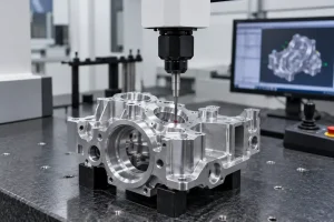
- Coordinate measuring machines (CMMs): Measure complex dimensions, surface profiles, and GD&T characteristics such as position and coaxiality.
- Vision measuring systems: Inspect small parts, thin components, hole locations, angles, and two-dimensional profiles.
- Optical comparators: Magnify part profiles to inspect angles, radii, threads, and complex edge features.
Complex 5-axis machined parts may require CMM inspection to verify positional tolerances and relationships between multiple surfaces. Inspectors must establish the correct datums and ensure that the inspection program matches the engineering drawing.
Surface and Material Testing Instruments
A machined part can meet its dimensional requirements and still fail because of poor surface condition, incorrect material composition, or improper heat treatment. These characteristics can affect wear resistance, fatigue life, sealing, and assembly performance.
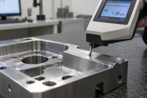
- Surface roughness testers: Measure parameters such as Ra and Rz to verify that the machined surface meets drawing requirements.
- Hardness testers: Check Rockwell, Brinell, or Vickers hardness after material processing or heat treatment.
- Metal analyzers and spectrometers: Identify chemical composition and verify that the material matches the specified grade.
The required tests should be determined by the material certificate, engineering drawing, and customer specifications.
Nondestructive Testing Equipment
Nondestructive testing equipment detects surface and internal defects without affecting the future use of the part.
- Liquid penetrant testing materials: Use cleaners, penetrants, and developers to reveal surface-breaking defects in nonporous materials.
- Magnetic particle testing equipment: Detect surface and near-surface defects in ferromagnetic materials.
- Ultrasonic testing equipment: Identify internal cracks, inclusions, laminations, and other discontinuities.
- Industrial radiographic equipment: Use X-ray imaging to locate internal porosity, inclusions, and volumetric defects.
The appropriate equipment depends on the part material, thickness, geometry, and target defect. Different nondestructive testing methods are not automatically interchangeable.
In-Process and Automated Inspection Systems
In-process inspection equipment collects measurement data during machining. It can help identify tool wear, machine offset, thermal distortion, and dimensional variation before these issues affect an entire production batch.
- CNC touch probes: Support workpiece setup, in-process measurement, and automatic offset compensation.
- Laser and machine vision systems: Inspect profiles, positions, dimensions, and visible surface defects.
- Automated data collection systems: Record inspection results, analyze process trends, and issue warnings when measurements approach tolerance limits.
Automated inspection can improve production efficiency, but critical parts may still require final verification using independent measuring equipment.
Quality Inspection Methods for Machined Parts
Quality inspection for machined parts extends beyond dimensional measurement. It can also include appearance, geometric tolerances, surface condition, material properties, and internal defects. The required inspection methods should be determined by the engineering drawing, intended application, and customer requirements.
Visual and Surface Defect Inspection
Visual inspection identifies observable machining and finishing defects. Inspectors may examine the part under controlled lighting with the unaided eye, magnification devices, or an industrial borescope.
Typical inspection points include:
- Burrs, dents, scratches, and corrosion
- Cracks, porosity, pits, and grinding burns
- Tool marks, chatter marks, and unusual machining patterns
- Coating, plating, identification, and color requirements
Visual inspection should use clearly defined acceptance criteria or approved reference samples instead of relying entirely on subjective judgment.
Dimensional Inspection
Dimensional inspection determines whether the actual dimensions of a machined part fall within the tolerances specified on the engineering drawing. It is one of the most fundamental parts of machining quality control.
Common inspection characteristics include:
- Length, width, thickness, and height
- Outside diameter, inside diameter, hole depth, and slot width
- Hole spacing, center distance, and step dimensions
- Threads, tapers, angles, and corner radii
Standard dimensions can be measured with calipers or micrometers. Tighter tolerances and complex features may require a vision measuring system or CMM. Dimensional inspection is especially important for CNC-milled parts with pockets, hole patterns, and multiple related surfaces.
Geometric Tolerance Inspection
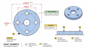
Geometric tolerance inspection verifies the shape of individual features and the positional relationships between them. The required datums must be established correctly before measurement; otherwise, the results may not reflect the part’s actual assembly condition.
Common GD&T characteristics include:
- Straightness, flatness, and circularity
- Parallelism, perpendicularity, and angularity
- Position, coaxiality, and symmetry
- Circular runout, total runout, and profile
Simple characteristics can be checked with a surface plate, indicators, and dedicated fixtures. More complex geometric tolerances usually require a CMM or specialized form-measuring equipment.
Surface Roughness Inspection
Surface roughness affects friction, sealing, fit, wear resistance, and fatigue performance. A surface should therefore not be accepted solely because it appears smooth to the eye.
During inspection:
- Measure the Ra, Rz, or other parameter specified on the drawing.
- Select the correct sampling and evaluation lengths.
- Measure in the appropriate direction to account for machining lay.
- Repeat measurements at multiple locations when required.
The results should be compared with the specified parameter and limit. Different roughness parameters should not be treated as directly interchangeable. Inspection requirements may also change after 表面处理, especially when coating thickness affects the final dimensions or fit.
Material and Mechanical Property Testing
Material and mechanical property testing confirms that the raw material, heat treatment, and surface treatment meet the functional requirements of the part. Material verification is particularly important for 铝数控加工 和 steel CNC machining because alloy grade and heat-treatment condition can affect part performance.
Common inspection items include:
- Material grade and chemical composition
- Rockwell, Brinell, or Vickers hardness
- Tensile strength, yield strength, and elongation
- Metallurgical structure and coating or plating thickness
Material composition and hardness can often be checked directly on the part or an accompanying test coupon. Tensile and impact testing usually require standardized specimens and may destroy the tested sample.
Nondestructive Testing
Nondestructive testing identifies surface or internal defects without impairing the serviceability of the part. It is commonly used for forgings, castings, welded components, and safety-critical machined parts subjected to high loads.
Common NDT methods include:
- Visual testing (VT): Identifies visible surface defects, machining abnormalities, and assembly issues.
- Liquid penetrant testing (PT): Reveals surface-breaking defects in nonporous materials.
- Magnetic particle testing (MT): Detects surface and near-surface defects in ferromagnetic materials.
- Ultrasonic testing (UT): Identifies internal cracks, inclusions, laminations, and other discontinuities.
- Radiographic testing (RT): Uses radiographic imaging to detect internal porosity, inclusions, and volumetric defects.
- Eddy current testing (ET): Detects surface and near-surface discontinuities in electrically conductive materials.
The appropriate method should be selected according to the material, part thickness, defect location, and applicable inspection standard. Testing and result interpretation should be performed by appropriately qualified personnel.
Functional and Assembly Verification
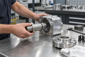
A part can meet every individual dimensional requirement and still fail in service because of tolerance accumulation, fit, or operating conditions. Trial assembly and functional testing may therefore be required.
Common verification items include:
- Shaft-to-hole fits and assembly clearances
- Thread engagement and locking performance
- Sealing and leak testing
- Locating, connection, and interchangeability
- Movement and operation of mechanical components
- Pressure, load, or operational performance
Functional verification should be performed with specified mating parts, inspection fixtures, and test conditions. Test parameters and final acceptance results should also be documented.
What Stages Are Included in CNC Machining Quality Inspection?
CNC machining quality inspection begins before production and continues until the finished parts are approved for shipment. A complete inspection process typically includes drawing review and inspection planning, incoming material inspection, first-article inspection, in-process inspection, final inspection, and pre-shipment review.
1. Drawing Review and Inspection Planning
Before machining begins, engineering and quality personnel review the engineering drawings, technical specifications, and customer requirements. They confirm dimensions, tolerances, GD&T requirements, critical quality characteristics, inspection methods, measuring tools, sampling frequency, and required quality documents. Proper inspection planning helps reduce measurement errors and ensures that important technical requirements are not overlooked.
2. Incoming Material Inspection
Incoming material inspection verifies that the material grade, dimensions, and technical properties meet the specified requirements. Inspectors may review material certificates, heat numbers, batch identification, and surface condition. Material composition or hardness may also be tested when required. Nonconforming materials should be identified and isolated before machining begins.
3. First-Article Inspection
First-article inspection is performed on the first completed part, or the first few parts, before full production begins. It verifies that the CNC program, cutting tools, fixtures, setup, and process parameters are correct. Batch production should begin only after the critical dimensions, GD&T characteristics, surface quality, machined features, and special requirements have been inspected and approved.
4. In-Process Inspection
In-process inspection monitors part quality at defined intervals during production. It helps identify tool wear, machine drift, thermal deformation, and setup changes before they affect an entire batch. Inspectors measure critical characteristics, monitor dimensional trends, record inspection results, and adjust tool offsets or process parameters when necessary.
5. Final Inspection
Final inspection takes place after all machining and finishing operations have been completed. Inspectors evaluate the finished parts against the engineering drawings, purchase order, and customer specifications. Depending on the requirements, final inspection may cover dimensions, GD&T, appearance, surface roughness, material properties, nondestructive testing, functional performance, surface treatments, and part identification.
6. Pre-Shipment Review and Quality Release
Before shipment, quality personnel review the finished parts and related documentation to confirm that the order is complete and ready for release. The review typically covers part numbers, quantities, inspection records, material certificates, special-process documents, packaging, and labels. Any nonconforming part must be identified, isolated, and reviewed before shipment.
How to Perform Quality Inspection on CNC-Machined Parts
The stages above explain when inspection takes place during production. The following procedure explains how an inspector carries out an individual quality inspection. The work should follow a consistent and repeatable process, from reviewing the engineering drawing to recording the results and controlling nonconforming parts.
1. Review the Drawings and Inspection Requirements
Begin by reviewing the engineering drawings, drawing revisions, customer specifications, and applicable standards. Identify the dimensional tolerances, GD&T requirements, surface roughness, material properties, and special quality characteristics that must be verified. Before inspection begins, confirm that the latest approved drawing revision is being used.
2. Prepare and Verify the Inspection Equipment
Select inspection tools with suitable accuracy, resolution, and measuring range based on the part tolerances, dimensions, and geometry. Confirm that the equipment is within its valid calibration period, and check it for damage, contamination, or zero errors. For precision measurement, allow the parts and equipment to stabilize in the inspection environment to reduce the effects of temperature variation.
3. Clean and Position the Part Correctly
Remove chips, cutting fluid, dust, and burrs that could affect the measurement results. Place the part on a clean, stable inspection surface and avoid clamping or supporting it in a way that could cause deformation. When inspecting GD&T characteristics, establish the datum reference frame specified on the engineering drawing.
4. Inspect the Specified Quality Characteristics
Inspect critical dimensions and functional features first, followed by general dimensions, geometric tolerances, surface roughness, appearance, and any required material or nondestructive tests. Use consistent measurement locations and operating methods to ensure that the results are repeatable and comparable.
5. Record and Evaluate the Inspection Results
Record the actual measured values, equipment identification, inspection date, part number, production batch, and inspector information. Compare each result with the specified drawing tolerance or acceptance criteria. A part should only be accepted after all required characteristics have been verified as compliant.
6. Control Nonconforming Parts and Reinspect Them
Clearly identify any nonconforming parts and separate them from acceptable products. Document and review the deviation before deciding whether the part should be reworked, repaired, accepted under an approved deviation, or scrapped. Reworked or repaired parts must be reinspected to confirm that they meet all applicable requirements.
How Does MinHe Ensure CNC Machining Quality?
At MinHe, quality control begins with drawing review before production and continues through process monitoring, final inspection, and shipment release. Under our ISO 9001-certified quality management system, we use defined inspection checkpoints, suitable measuring equipment, and traceable quality documentation to control the quality of each project. You can learn more about MinHe’s CNC machining capabilities and manufacturing approach on our company page.
Review Quality Requirements Before Production
Before machining begins, MinHe’s engineering team reviews the drawings, materials, tolerances, and surface finishing requirements. This allows us to identify technical risks that could affect machining quality.
- Drawing and revision review: Confirm that production uses the latest approved engineering drawings and technical specifications.
- Critical feature identification: Highlight dimensions and tolerances that affect function, assembly, and performance.
- DFM analysis: Provide recommendations when a feature may be difficult to machine, measure, or control consistently.
- Inspection planning: Select suitable measuring tools, inspection equipment, and inspection frequency based on the part geometry and tolerances.
Verify Materials and Traceability Information
MinHe verifies incoming materials according to the project requirements, helping prevent incorrect material grades, specifications, or conditions from affecting part performance.
- Material verification: Confirm that the material grade and specification match the order requirements.
- Batch traceability: Record applicable heat numbers, batch numbers, or supplier information.
- Material documentation: Review or provide material certificates when required.
- Material isolation: Prevent nonconforming materials from being used until the issue has been reviewed.
Perform First-Article and In-Process Inspection
Before batch production, MinHe performs first-article inspection to verify the CNC program, tools, fixtures, and process parameters. During production, critical dimensions are monitored at defined checkpoints to prevent deviations from affecting the entire batch.
- First-article verification: Check critical dimensions, GD&T characteristics, machined features, and surface condition.
- Critical-operation checks: Verify relevant dimensions after important machining operations.
- In-process monitoring: Measure critical quality characteristics at specified intervals.
- Process adjustment: Investigate tool wear, workholding, and machine conditions when dimensional variation is detected.
Use Suitable Inspection Equipment
MinHe selects inspection tools according to the size, tolerance, and geometry of each part. Standard measuring tools are used for general dimensions, while a coordinate measuring machine can verify complex features and tighter tolerances.
- Standard measuring tools: Use calipers, micrometers, gauges, and indicators to inspect general dimensions.
- Dedicated gauges: Use plug, ring, and thread gauges to quickly verify critical features.
- CMM inspection: Measure complex dimensions, positional relationships, and specified geometric tolerances.
- Equipment calibration: Maintain and calibrate inspection equipment according to quality management requirements.
Complete Final Inspection and Quality Release
After all machining and finishing operations have been completed, quality personnel inspect the finished parts against the approved drawings and order requirements. Parts are not released for shipment until the required checks have been completed.
- Dimensional inspection: Confirm that critical dimensions and specified tolerances meet the drawing requirements.
- Visual inspection: Check for burrs, scratches, dents, corrosion, and surface-finishing issues.
- Order verification: Confirm part numbers, quantities, identification, and revision information.
- Packaging inspection: Apply suitable protection based on the material and surface requirements of the parts.
Provide Quality Documentation When Required
For projects that require inspection and traceability records, MinHe can provide relevant quality documents based on the agreed requirements. These documents give customers clearer evidence of the inspection results.
Available documents may include:
- Dimensional inspection reports
- First-article inspection reports
- CMM inspection reports
- Material certificates
- Other agreed quality documents
Through pre-production review, in-process control, final inspection, and documentation, MinHe helps reduce the risk of nonconforming parts reaching customer assembly lines or end-use applications.
结论
Effective quality control in CNC machining requires more than checking finished dimensions. It combines suitable inspection methods and tools with drawing review, material verification, first-article approval, in-process monitoring, final inspection, and traceable documentation. The specific inspection plan should always reflect the part geometry, tolerances, material, function, and customer requirements.
At MinHe, quality control is integrated throughout the machining process to identify deviations early and reduce the risk of nonconforming parts reaching customer assembly lines. Send us your drawings with the required material, tolerances, surface finish, and inspection documents to receive DFM feedback and a quotation.