

CAD-Modelle können nicht direkt von CNC-Maschinen gefertigt werden, da ihnen die für das Schneiden erforderlichen spezifischen Bewegungsanweisungen fehlen. CAM (Computer-Aided Manufacturing) dient als Brücke, um digitale Entwürfe in umsetzbare Werkzeugwege und G-Code umzuwandeln.
In diesem Artikel wird erläutert, was CAM ist, wie der Programmierworkflow funktioniert und warum er für die moderne Präzisionsfertigung unerlässlich ist.
Was ist CAM?
CAM bezieht sich auf die Verwendung von Software zur Planung und Steuerung des Produktionsprozesses von CNC-Werkzeugmaschinen (Computer Numerical Control).
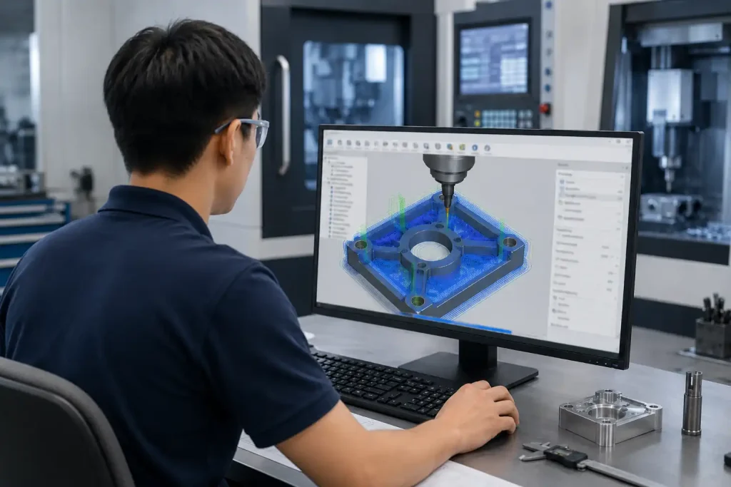
Vereinfacht ausgedrückt, unterstützt CAM-Software den Programmierer bei der Planung der Bewegungslogik einer Werkzeugmaschine. Sie liest die von CAD generierten 3D-Modelle ein, berechnet die Werkzeugbewegungspfade auf der Grundlage vorgegebener Bearbeitungsprozesse und wandelt diese Pfade in Anweisungen um, die von den Maschinensteuerungen erkannt werden können - der sogenannte G-Code.
Eine kurze Geschichte von CAM
Die Entwicklung der CAM ist eng mit der Entwicklung der numerisch gesteuerten Bearbeitung verbunden. In der Frühphase der Fertigungsautomatisierung wurden Werkzeugmaschinen durch manuell geschriebene Anweisungen oder Lochstreifensysteme gesteuert. Programmierer mussten Werkzeugbewegungen, Koordinaten, Vorschübe und Geschwindigkeiten weitgehend von Hand berechnen, was die komplexe Bearbeitung zeitaufwändig und fehleranfällig machte.
Mit der zunehmenden Verbreitung von CNC-Maschinen brauchten die Hersteller eine schnellere und zuverlässigere Methode, um Konstruktionsentwürfe in Bearbeitungsprogramme umzusetzen. CAM-Software wurde nach und nach entwickelt, um dieses Problem zu lösen. Anstatt jede Maschinenbewegung manuell zu beschreiben, konnten Programmierer digitale Modelle verwenden, um Werkzeugwege zu erstellen, Bearbeitungsvorgänge zu simulieren und maschinenspezifischen G-Code zu erzeugen.
Mit dem Aufkommen von 3D-CAD, mehrachsigen CNC-Maschinen und digitalen Fertigungsabläufen wurde CAM ein wesentlicher Bestandteil der modernen Bearbeitung. Heute wird CAM nicht nur für einfache fräsen und Drehbearbeitung, aber auch für die 3D-Oberflächenbearbeitung, den Formenbau, die 5-Achs-Bearbeitung, die Prototypenfertigung und die Herstellung komplexer Präzisionsteile.
Wie funktioniert CAM?
Der CAM-Arbeitsablauf umfasst in der Regel die folgenden standardisierten Phasen:
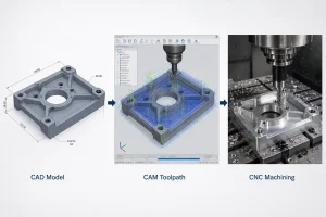
1. CAD-Datei Import
Der Prozess beginnt mit dem Importieren der CAD-Modell in die CAM-Software ein. Der Programmierer prüft die Modellmerkmale, um die Bearbeitungsanforderungen, Toleranzstandards und die optimale Bearbeitungsausrichtung zu bestimmen.
2. Werkstück- und Koordinateneinstellung
Definieren Sie die Rohteilabmessungen und legen Sie das Werkstückkoordinatensystem (WCS) fest, um sicherzustellen, dass das digitale Modell genau auf das physische Werkstück auf dem Maschinentisch ausgerichtet ist.
3. Auswahl der Bearbeitungsstrategie
Wählen Sie geeignete Strategien auf der Grundlage der Teilemerkmale. So wird beispielsweise das Schruppen für einen schnellen Materialabtrag verwendet, während die Schlichtzyklen eingesetzt werden, um eine hohe Oberflächenqualität zu erreichen und die Maßtoleranzen einzuhalten.
4. Werkzeugweggenerierung
Die Software berechnet die Fräsbahnen. Der Programmierer stellt technische Parameter wie Spindeldrehzahlen, Vorschubgeschwindigkeiten und Schnitttiefen auf der Grundlage von Materialeigenschaften und Werkzeugspezifikationen ein.
5. Simulation und Verifizierung
Vor der Codegenerierung führt der Programmierer eine vollständige Prozesssimulation in der Software durch. Dieser Schritt ist wichtig, um die Werkzeugwege zu überprüfen und mögliche Interferenzen oder Kollisionsrisiken zwischen dem Schneidwerkzeug, den Vorrichtungen und der Maschine auszuschließen.
6. Post-Processing-Ausgabe
Die optimierten Werkzeugwege werden durch einen Postprozessor in eine maschinenspezifische G-Code-Datei umgewandelt, die die für die CNC-Maschinensteuerung erforderlichen präzisen Anweisungen enthält.
Was sind die Vorteile von CAM für die CNC-Bearbeitung?
Im Vergleich zur manuellen Programmierung bietet CAM deutliche Vorteile, die den CNC-Bearbeitungsprozess direkt verbessern:
- Effizienter Materialabtrag: Fortschrittliche Strategien (wie Trochoidal- oder Hochgeschwindigkeitsbearbeitung) sorgen für gleichmäßige Schnittkräfte, erhöhen das Zeitspanvolumen und verlängern die Werkzeugstandzeit.
- Fähigkeit zu komplexer Formgebung: CAM-Software verarbeitet komplexe 3D-Konturen und mehrachsige Bewegungen, die manuell nur schwer zu programmieren sind, und ermöglicht so die Herstellung anspruchsvoller Formen.
- Verringerung der Maschinenstillstandszeiten: Da die Simulationsfunktionen Kollisionen und Fugenabweichungen in einer virtuellen Umgebung erkennen, wird der Bedarf an zeitaufwändigen Testläufen auf der physischen Maschine minimiert.
- Konsistente Qualität und Optimierung: Durch standardisierte Prozessvorlagen und Werkzeugbibliotheken stellt CAM sicher, dass die Bearbeitungsparameter zwischen verschiedenen Bedienern konsistent bleiben, wodurch die Variabilität der Oberflächengüte und der Maßgenauigkeit verringert wird.
Branchenübergreifende CAM-Anwendungen
Die CAM-Technologie spielt in mehreren Fertigungsbereichen eine wichtige Rolle:
- Luft- und Raumfahrt: Durch den Einsatz effizienter Zerspanungsstrategien hilft CAM, die Werkzeugbelastung bei der Bearbeitung von Materialien wie Titan zu optimieren und eine hohe Oberflächenqualität zu erreichen.
- Automobilherstellung: Mit intelligenten Lösungen für die Formenbearbeitung hilft es bei der Bearbeitung großer und komplexer Kavitäten und trägt dazu bei, die Zyklen der Formenherstellung zu verkürzen.
- Medizinische Geräte: Mit einer präzisen Bahnsteuerung hilft sie bei der Bearbeitung von Implantaten wie künstlichen Gelenken aus Titan, um die Anforderungen an komplexe morphologische Formen zu erfüllen.
- Unterhaltungselektronik: Durch die Mehrachsen-Verknüpfungsfunktionen hilft sie bei der Durchführung komplexer Mehrseitenbearbeitungen, z. B. bei Handyrahmen, und trägt dazu bei, Fehler durch wiederholtes Einspannen zu reduzieren.
- Allgemeine Präzisionsteile: Durch die automatische Optimierung der Werkzeugwege unterstützt es den Übergang von der Einzelteil- zur Serienfertigung und hilft so, die Stückkosten während des Bearbeitungsprozesses zu senken.
Was sind beliebte CAM-Software-Tools?
Die gängige CAM-Software variiert je nach Schwerpunkt; im Folgenden werden einige in der Branche gängige Tools vorgestellt:
- Siemens NX (NX CAM): Weit verbreitet in der Fertigung, insbesondere bei der komplexen Mehrachsenbearbeitung.
- Autodesk Fusion 360: Bietet Funktionen für die Zusammenarbeit in der Cloud und eine intuitive Benutzeroberfläche, die häufig von kleinen bis mittleren Unternehmen und für das Produktprototyping verwendet wird.
- Mastercam: Verfügt über ausgereifte Funktionen und wird in vielen Werkstätten eingesetzt.
- Autodesk PowerMill: Hat großen Einfluss in den Bereichen der komplexen Oberflächenbearbeitung und des Formenbaus.
- HyperMill: Sie ist bekannt für ihre intelligenten Bearbeitungsstrategien und wird von vielen Ingenieuren für die Bearbeitung von High-End-Teilen bevorzugt.
Mainstream CAM Software Übersicht
| Software-Werkzeug | Primäre Stärken | Gemeinsame Bewerbung | Unterstützte Dateiformate |
| Siemens NX | Fortgeschrittene mehrachsige und komplexe Bearbeitung | Großserienfertigung | .prt, .step, .x_t, .igs |
| Autodesk Fusion 360 | Cloud-Zusammenarbeit & intuitive Benutzeroberfläche | Prototyping & KMU | .f3d, .step, .iges, .dxf |
| Mastercam | Ausgereifte, dem Industriestandard entsprechende Funktionalität | Allgemeine Maschinenbaubetriebe | .mcam, .step, .iges, .dxf, .dwg |
| Autodesk PowerMill | Spezialisiert auf Oberflächenveredelung | Herstellung von Formen und Gesenken | .dgk, .step, .iges, .x_t |
| HyperMill | Intelligente Bearbeitungsstrategien | Hochwertige Präzisionsteile | .hmf, .step, .x_t, .iges |
Welche Qualifikationen sind für CAM erforderlich?
Um ein kompetenter CAM-Programmierer zu werden, ist in der Regel eine Kombination mehrerer Fähigkeiten erforderlich:
- Kenntnisse in der maschinellen Bearbeitung: Verstehen der Grundsätze der Zerspanung, der Werkzeugauswahl, der Materialeigenschaften und der Konstruktion von Vorrichtungen.
- Software-Kenntnisse: Beherrschung mindestens einer gängigen CAM-Plattform.
- Blueprint Literacy: Genaue Interpretation von technischen Zeichnungen, einschließlich GD&T, Gewindeanforderungen und Normen für die Oberflächengüte.
- Analytisches Denken: Fähigkeit zur Diagnose und Anpassung von Parametern zur Lösung von Problemen wie Vibrationen, Maßabweichungen oder Werkzeugverschleiß.
Schlussfolgerung
Die CAM-Programmierung wandelt Konstruktionsentwürfe in physische Teile um und verbessert sowohl die Produktionseffizienz als auch die Produktqualität. Durch standardisierte Prozessplanung, sinnvolle Bearbeitungsstrategien und strenge Simulationsprüfungen können Programmierer die Maschinenleistung maximieren und die Zuverlässigkeit in der Produktion sicherstellen. Mit der fortschreitenden Modernisierung der Fertigung ist die Beherrschung der CAM-Technologie ein wichtiger Weg zur Verbesserung der Konstruktions- und Fertigungsfähigkeiten geworden.