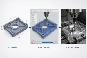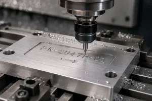

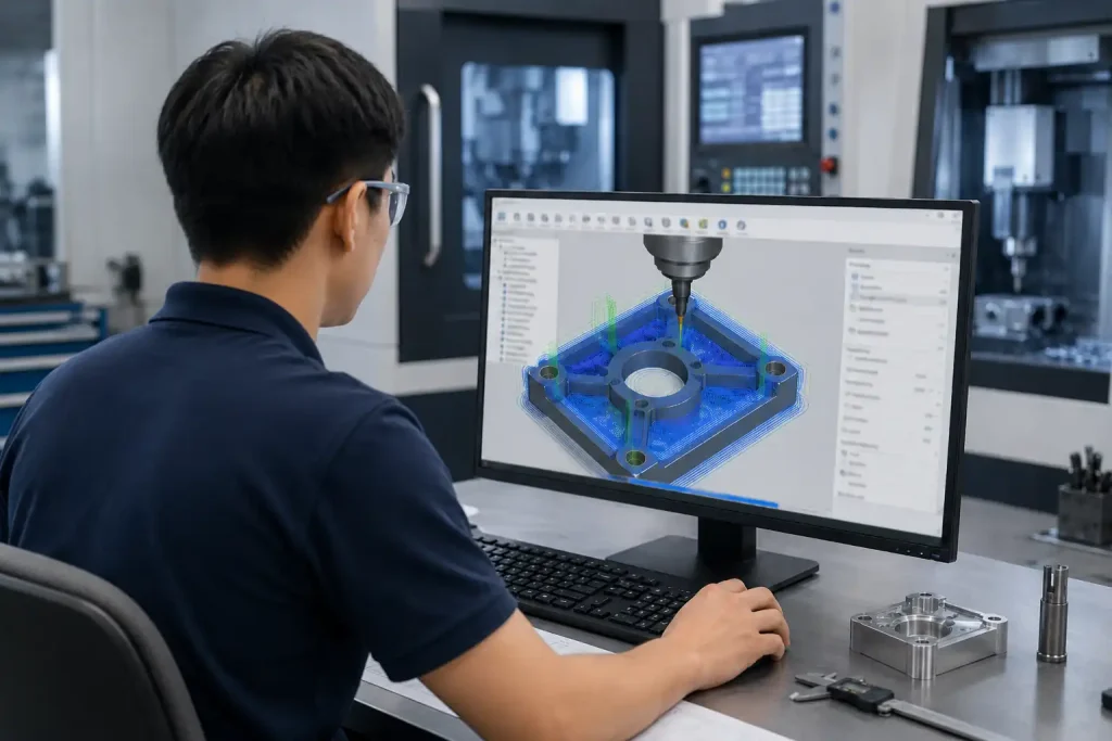
CAD models cannot be directly manufactured by CNC machines, as they lack the specific motion instructions required for cutting. CAM (Computer-Aided Manufacturing) serves as the bridge, transforming digital designs into actionable toolpaths and G-code.
This article explores what CAM is, how the programming workflow functions, and why it is essential for modern precision manufacturing.
What is CAM?
CAM refers to the use of software to plan and control the production process of CNC (Computer Numerical Control) machine tools.
In simple terms, CAM software assists programmers in planning the motion logic of a machine tool. It reads the 3D models generated by CAD, calculates tool movement paths based on pre-set machining processes, and converts these paths into instructions that machine controllers can recognize—known as G-code.
A Brief History of CAM
The development of CAM is closely related to the evolution of numerical control machining. In the early stage of manufacturing automation, machine tools were controlled by manually written instructions or punched tape systems. Programmers had to calculate tool movements, coordinates, feeds, and speeds largely by hand, which made complex machining time-consuming and error-prone.
As CNC machines became more common, manufacturers needed a faster and more reliable way to convert engineering designs into machining programs. CAM software gradually developed to solve this problem. Instead of manually describing every machine movement, programmers could use digital models to create toolpaths, simulate machining operations, and generate machine-specific G-code.
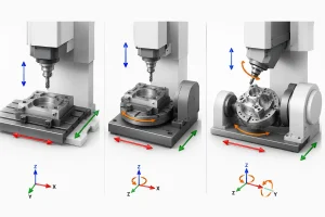
With the growth of 3D CAD, multi-axis CNC machines, and digital manufacturing workflows, CAM became an essential part of modern machining. Today, CAM is used not only for simple ミーリング and turning operations, but also for 3D surface machining, mold making, 5-axis machining, prototype production, and complex precision parts manufacturing.
How does CAM work?
The CAM workflow typically includes the following standardized stages:
1. CAD File Import
The process begins by importing the CAD model into the CAM software. The programmer reviews the model features to determine machining requirements, tolerance standards, and optimal machining orientation.
2. Workpiece and Coordinate Setup
Define the raw stock dimensions and establish the Work Coordinate System (WCS), ensuring that the digital model is accurately aligned with the physical workpiece on the machine table.
3. Machining Strategy Selection
Select appropriate strategies based on part features. For instance, roughing is used for rapid material removal, while finishing cycles are employed to achieve high surface quality and meet dimensional tolerances.
4. Toolpath Generation
The software calculates cutting trajectories. The programmer sets technical parameters, such as spindle speeds, feed rates, and cutting depths, based on material properties and tool specifications.
5. Simulation and Verification
Before generating code, the programmer performs a full-process simulation within the software. This step is critical to verify toolpaths and check for any potential interference or collision risks between the cutting tool, fixtures, and the machine.
6. Post-Processing Output
The optimized toolpaths are converted through a post-processor into a machine-specific G-code file, providing the precise instructions required for the CNC machine controller.
What are the Benefits of CAM for CNC Machining?
Compared to manual programming, CAM offers distinct advantages that directly improve the CNC machining process:
- Efficient Material Removal: Advanced strategies (such as trochoidal or high-speed machining) maintain consistent cutting loads, increasing metal removal rates and extending tool life.
- Complex Shape Capability: CAM software handles complex 3D contours and multi-axis movements that are difficult to program manually, enabling the production of sophisticated shapes.
- Reduction of Machine Downtime: Because simulation functions detect collisions and gouging errors in a virtual environment, the need for time-consuming test runs on the physical machine is minimized.
- Consistent Quality and Optimization: Through standardized process templates and tool libraries, CAM ensures that machining parameters remain consistent across different operators, reducing variability in surface finish and dimensional accuracy.
CAM Applications Across Industries
CAM technology plays an important role in several manufacturing sectors:
- 航空宇宙 Utilizing efficient cutting strategies, CAM helps optimize tool loads when machining materials like titanium, striving for high surface quality.
- 自動車製造: Relying on intelligent mold machining solutions, it assists in handling large and complex mold cavities, helping to shorten mold manufacturing cycles.
- 医療機器 With precise path control, it assists in machining implants like titanium artificial joints, striving to meet requirements for complex morphological forms.
- Consumer Electronics: Through multi-axis linkage functions, it assists in completing complex multi-side machining for items like mobile phone frames, helping to reduce errors caused by repeated clamping.
- General Precision Parts: Through automated toolpath optimization, it assists in the transition from single-piece prototyping to batch production, helping to reduce unit costs during the machining process.
What are Popular CAM Software Tools?
Mainstream CAM software varies by focus; the following are some common tools in the industry:
- Siemens NX (NX CAM): Widely used in manufacturing, especially prevalent in complex multi-axis machining.
- Autodesk Fusion 360: Features cloud collaboration capabilities and an intuitive interface, often used by small-to-medium enterprises and for product prototyping.
- Mastercam: Features mature functionality and is applied in many machine shops.
- Autodesk PowerMill: Holds significant influence in the fields of complex surface finishing and mold manufacturing.
- HyperMill: Known for its high level of intelligent machining strategies, it is favored by many engineers for high-end part machining.
Mainstream CAM Software Overview
| Software Tool | Primary Strengths | Common Application | Supported File Formats |
| Siemens NX | Advanced multi-axis & complex machining | Large-scale manufacturing | .prt, .step, .x_t, .igs |
| Autodesk Fusion 360 | Cloud collaboration & intuitive UI | Prototyping & SMEs | .f3d, .step, .iges, .dxf |
| Mastercam | Mature, industry-standard functionality | General machine shops | .mcam, .step, .iges, .dxf, .dwg |
| Autodesk PowerMill | Specialized in surface finishing | Mold & die manufacturing | .dgk, .step, .iges, .x_t |
| HyperMill | Intelligent machining strategies | High-end precision parts | .hmf, .step, .x_t, .iges |
What Skills are Required for CAM?
Becoming a proficient CAM programmer typically requires a combination of several abilities:
- Machining Knowledge: Understanding cutting principles, tool selection, material properties, and fixture design.
- Software Skills: Mastering at least one mainstream CAM platform.
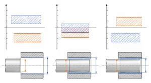
- Blueprint Literacy: Accurately interpreting engineering drawings, including GD&T, thread requirements, and surface finish standards.
- Analytical Thinking: Ability to diagnose and adjust parameters to resolve issues like vibration, dimensional deviations, or tool wear.
結論
CAM programming converts engineering designs into physical parts, enhancing both production efficiency and product quality. Through standardized process planning, sensible machining strategies, and rigorous simulation verification, programmers can maximize machine performance and ensure reliability in production. As manufacturing continues to upgrade, mastering CAM technology has become a key path to improving engineering and manufacturing capabilities.