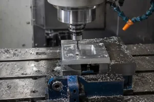

Im Bereich der Präzisionsfertigung sind die CNC-Bearbeitungstoleranzen ein wichtiger Indikator für die Qualität der Teile und die Fertigungsfähigkeit. Obwohl moderne CNC-Maschinen eine extrem hohe Präzision erreichen können, führt das blinde Streben nach maximaler Genauigkeit in der tatsächlichen Produktion oft zu steigenden Kosten und geringerer Effizienz. Ein ausgezeichnetes technisches Design sollte durch wissenschaftliche Toleranzzuweisung ein Gleichgewicht zwischen Teileleistung, Bearbeitungskosten und Ausschussrate herstellen und gleichzeitig die funktionalen Anforderungen des Produkts erfüllen. Dieser Artikel bietet einen detaillierten Einblick in die Grundkenntnisse der CNC-Toleranzen und ihre Anwendungen in der Fertigung.
Was ist eine CNC-Bearbeitungstoleranz?
Die Toleranz bezieht sich auf die zulässige Schwankungsbreite für ein Werkstückmaß während des CNC-Bearbeitungsprozesses. In mechanischen Konstruktionszeichnungen geben die Konstrukteure in der Regel ein Zielmaß (Nennmaß) an, und die Toleranz definiert den Spielraum, in dem das fertige Teil von diesem Zielmaß abweichen darf. Einfach ausgedrückt: Solange das tatsächliche Bearbeitungsergebnis innerhalb dieses Bereichs liegt, wird es als akzeptables Produkt betrachtet.
Wenn zum Beispiel der Zieldurchmesser eines Präzisionslagersitzes 20,00 mm mit einer festgelegten Toleranz von ± 0,01 mmjedes fertige Teil mit einer Größe zwischen 19,99 mm und 20,01 mm sorgt für einen reibungslosen Zusammenbau. Wenn die Toleranz angezogen wird auf ± 0,002 mmObwohl die Präzision höher ist, steigen die Anforderungen an die Maschinenstabilität, den Werkzeugverschleiß und die Umgebungstemperatur exponentiell an, was sich direkt auf die Fertigungsschwierigkeiten auswirkt.
Übliche CNC-Bearbeitungstoleranzbereiche
CNC-Bearbeitungstoleranzen variieren je nach Teilegröße, Material, Geometrie, Bearbeitungsprozess und Prüfverfahren. In der Praxis verwenden Konstrukteure oft allgemeine Toleranznormen als Ausgangspunkt für Abmessungen, die keine individuellen Toleranzangaben haben. Ein gängiges Beispiel ist ISO 2768-1die lineare Abmessungen nach Größenbereich und Toleranzklasse gruppiert.
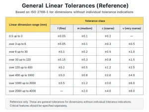
Diese Art von Diagramm ist nützlich, um gängige Toleranzbereiche für gewöhnliche Abmessungen zu verstehen. Sie sollte jedoch als allgemeine Referenz und nicht als festes Bearbeitungsversprechen betrachtet werden. Kritische Merkmale wie Passbohrungen, Anschlagflächen, Dichtungsflächen und Präzisionsanpassungsflächen sollten weiterhin separat entsprechend den funktionalen Anforderungen spezifiziert werden.
Gängige Arten von CNC-Bearbeitungstoleranzen
In der Praxis wählen Ingenieure bestimmte Toleranzformate aus, je nachdem, wie ein Teil funktionieren und mit anderen Komponenten zusammengefügt werden soll. Das Verständnis dieser gängigen Typen ist für die Interpretation von technischen Zeichnungen und die Gewährleistung der Machbarkeit der Herstellung von entscheidender Bedeutung:
1. Bilaterale Toleranz
Dies ist die am weitesten verbreitete Form der Toleranz, die in der Regel durch die ± Symbol. Es gibt an, dass ein Maß gleichermaßen in positiver und negativer Richtung vom Nennwert abweichen kann. Zum Beispiel, 30,00 ± 0,05 mm bedeutet, dass jede Dimension zwischen 29,95 mm und 30,05 mm ist akzeptabel. Dieses Format ist einfach strukturiert und wird üblicherweise für allgemeine Strukturteile und nicht zusammenpassende Abmessungen verwendet.
2. Einseitige Duldung
Die einseitige Toleranz erlaubt die Abweichung eines Maßes in nur einer Richtung (entweder positiv oder negativ). Dies ist für Teile mit engen Passungen entscheidend. Um zum Beispiel sicherzustellen, dass ein Stift immer in eine Bohrung eingeführt werden kann, wird die Toleranz für den Bohrungsdurchmesser oft wie folgt angegeben +0,02 / -0,00 mm um sicherzustellen, dass das Loch nicht kleiner wird. Diese Beschriftungsmethode vermittelt dem Maschinenbauer eindeutig die Absicht der Montage.
3. Grenzwerttoleranz
Bei der Grenztoleranz wird kein Nennmaß angegeben, sondern es werden direkt die maximal und minimal zulässigen Werte gekennzeichnet. Ein Etikett könnte zum Beispiel lauten 15,00-15,02 mm. Dieses Layout erleichtert Qualitätsprüfern und Bedienern die Arbeit erheblich, da sie keine Addition oder Subtraktion durchführen müssen, um direkt anhand der Messwerte festzustellen, ob ein Teil außerhalb der Toleranz liegt.
4. Passform-Toleranz
Die Passungstoleranz basiert in erster Linie auf ISO-Normen (z. B. H7, g6) und wird speziell zur Beschreibung der Montageart zwischen einer Bohrung und einer Welle verwendet. Sie ist nicht nur eine Reihe von Werten, sondern gibt an, ob es sich bei der Beziehung zwischen den Teilen um eine Spielpassung (frei drehbar), eine Übergangspassung (präzise Positionierung) oder eine Presspassung (Presspassung) handelt. Sie ist der Schlüssel zu einer standardisierten Fertigung in der feinmechanischen Konstruktion.
5. Geometrische Dimensionierung und Tolerierung (GD&T)
Im Gegensatz zu linearen Standardtoleranzen, die die Größe kontrollieren, steuert GD&T die Form, die Ausrichtung und die Position von Merkmalen. Dabei wird eine Reihe von Symbolen verwendet, um Merkmale wie Ebenheit, Parallelität und Position zu definieren. Eine Oberfläche kann beispielsweise die Dickentoleranz erfüllen, aber verzogen sein; GD&T stellt sicher, dass die Oberfläche flach genug für eine ordnungsgemäße Abdichtung bleibt. Dies ist wichtig für hochpräzise Komponenten, bei denen die Beziehung zwischen den verschiedenen Merkmalen ebenso wichtig ist wie ihre individuelle Größe.
Wie bestimmt man die richtige Toleranz?
Die Wahl der Toleranzen sollte keine Frage des Ratens sein, sondern eine kalkulierte Entscheidung, die auf der Funktionalität des Teils und der Fertigungsintegration beruht. Hier ist der effektive Weg zur Definition des richtigen Toleranzbereichs:
1. Unterscheidung zwischen funktionalen und nicht-funktionalen Oberflächen
Nicht jedes Maß ist kritisch. Beginnen Sie mit der Kategorisierung von Merkmalen: Für nicht funktionale Oberflächen (wie dekorative Kanten oder Taschen zur Gewichtsreduzierung) wird empfohlen, allgemeine Toleranznormen (wie ISO 2768-m) anzuwenden. Strenge Toleranzen sollten ausschließlich für funktionelle Oberflächen reserviert werden, die für die Abdichtung, das Tragen von Lasten oder die Bewegungsanpassung erforderlich sind.
2. Wählen Sie einen erfahrenen CNC-Bearbeitungspartner
Das Erreichen des idealen Montageergebnisses hängt oft von der genauen Abstimmung zwischen Konstruktionsabsicht und Fertigungslogik ab. In der täglichen Arbeit von Minghe CNC Machining Services stellen wir häufig fest, dass die Werkstätten, wenn in den Zeichnungen keine expliziten Anforderungen enthalten sind, in der Regel eine "allgemeine Standardpräzision" wählen (oft etwa ± 0,1 mm). Diese Abweichung mag für das bloße Auge vernachlässigbar erscheinen, doch in der Feinmechanik ist selbst eine 0,005-Zoll-Abweichung reicht aus, um das empfindliche physikalische Gleichgewicht zwischen einer Bohrung und einem Schaft zu stören. Wenn Sie mit einem Anbieter zusammenarbeiten, der der Kommunikation in der Vorproduktionsphase Priorität einräumt, erhalten Sie fachkundige Optimierungsempfehlungen, die auf spezifische Materialeigenschaften (z. B. thermische Ausdehnung oder Spannungsentlastung) zugeschnitten sind, wodurch die versteckten Risiken von Standardnormen gemindert und gleichzeitig die Nachbearbeitungskosten erheblich gesenkt werden.
3. Priorisierung von Industriestandards und Fit-Klassen
Für die meisten standardisierten Bauteile (wie Lagersitze oder Spannstiftbohrungen) gibt es in der Industrie bereits ausgereifte Toleranzklassentabellen (z. B. H7/h6). Die Bevorzugung dieser Standardwerte bei der Konstruktion verbessert nicht nur die Austauschbarkeit und Zuverlässigkeit der Teile, sondern senkt auch die Prüfkosten durch die Verwendung von Standardmesswerkzeugen.
4. Bewertung der Montagetoleranzabstufung
In Baugruppen, die aus mehreren Komponenten zusammengesetzt sind, häufen sich während des Montageprozesses winzige Abweichungen bei den einzelnen Teilen. Durch die Durchführung einer Analyse der Toleranzabstufungkönnen Sie feststellen, ob es notwendig ist, die Toleranzen bei bestimmten kritischen Teilen zu verringern, um die Endmontagegenauigkeit der gesamten Maschine zu gewährleisten und so ein optimales Verhältnis zwischen Gesamtkosten und Leistung zu erreichen.
Schlussfolgerung
CNC-Bearbeitungstoleranzen wirken sich direkt darauf aus, ob ein Teil korrekt zusammengebaut werden kann, zuverlässig funktioniert und zu angemessenen Kosten hergestellt werden kann. Eine klare Toleranzstrategie hilft bei der Bestimmung, welche Merkmale eine enge Kontrolle erfordern, welche Abmessungen allgemeinen Standards folgen können und wie Bearbeitung, Prüfung und Nachbearbeitung vor Produktionsbeginn geplant werden sollten.
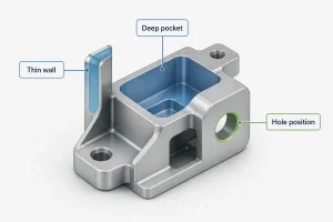
Bei Projekten mit engen Passungen, Passbohrungen, dünnen Wänden, mehrseitigen Bearbeitungen oder sekundären Nachbearbeitungsanforderungen sollte die Überprüfung der Toleranzen nicht erst in späteren Phasen der Produktion erfolgen. Sie sollte Teil der frühen DFM-Bewertung sein. Dies trägt dazu bei, das Nacharbeitsrisiko zu verringern, unnötige Überpräzision zu vermeiden und die Konsistenz der fertig bearbeiteten Teile zu verbessern.
Wir bei Minghe unterstützen CNC-Bearbeitungsprojekte von der Zeichnungsprüfung bis zur Produktionslieferung und helfen unseren Kunden bei der Bewertung der Toleranzanforderungen auf der Grundlage von Teilefunktion, Materialverhalten, Bearbeitungsmethode und Prüfanforderungen. Wenn Ihr Projekt CNC-Fräsen, 5-Achsen-Bearbeitung, CNC-Drehen oder Oberflächenveredelung umfasst, kann unser Ingenieurteam Ihnen helfen, Ihre Zeichnungen vor der Fertigung zu überprüfen und einen praktikablen Toleranzansatz zu empfehlen.
FAQ
Gibt es eine feste Toleranztabelle für die CNC-Bearbeitung?
Es gibt keine einzige feste Toleranztabelle, die für alle CNC-gefertigten Teile gilt. Viele Werkstätten haben ihre eigenen Standard-Bearbeitungstoleranzen, und die allgemeinen Abmessungen können in etwa wie folgt kontrolliert werden ± 0,10 mm oder einen ähnlichen Bereich. Die tatsächliche Toleranz hängt jedoch immer noch von Material, Teilegröße, Geometrie, Bearbeitungsmethode und Prüfanforderungen ab. Passbohrungen, Anschlagflächen und Präzisionsmontagemaße sollten in der Regel separat auf der Zeichnung angegeben werden.
Wie werden die Standard-Bearbeitungstoleranzen normalerweise bestimmt?
Standard-Bearbeitungstoleranzen werden in der Regel durch den Zeichnungstitel, technische Hinweise, firmeninterne Normen oder allgemeine Normen bestimmt. Zum Beispiel können Maße ohne individuelle Toleranzangaben wie folgt lauten ISO 2768 oder die Standardnorm des Bearbeitungsunternehmens. Allgemeintoleranzen eignen sich vor allem für unkritische Maße, während funktionale Merkmale weiterhin entsprechend den Montage- und Leistungsanforderungen definiert werden sollten.
Sind 0,005 mm eine enge Toleranz?
Ja. 0,005 mm ist eine sehr enge Toleranz für die meisten CNC-Bearbeitungsprojekte. Sie erfordert in der Regel stabile Maschinenbedingungen, Präzisionsvorrichtungen, strenge Inspektionskontrollen und manchmal sekundäre Endbearbeitungsprozesse wie Schleifen oder Honen. Für gewöhnliche Konstruktionsmaße sollte dieses Toleranzniveau nicht standardmäßig angewendet werden.
Was ist der Unterschied zwischen CNC-Drehtoleranz und CNC-Frästoleranz?
CNC-Drehen wird in der Regel für Rotationsteile wie Wellen, Hülsen, Buchsen und Flansche verwendet. Zu den häufig kontrollierten Merkmalen gehören Außendurchmesser, Innendurchmesser, Stirnflächen und konzentrische Merkmale. CNC-Fräsen wird häufiger für Halterungen, Gehäuse, Platten, Schlitze, Löcher, Taschen und mehrseitige Teile verwendet, bei denen die Toleranzkontrolle durch Einrichtungsänderungen, tiefe Hohlräume, dünne Wände und mehrseitige Bearbeitung beeinträchtigt werden kann. Ihre Toleranzfähigkeit sollte auf der Grundlage der spezifischen Teilemerkmale bewertet werden, anstatt sie allgemein zu vergleichen.
Wie liest man die Symbole für Bearbeitungstoleranzen?
Das gebräuchlichste Symbol für die Bearbeitungstoleranz ist ±. Zum Beispiel, 20,00 ± 0,05 mm bedeutet, dass die Abmessung innerhalb folgender Grenzen variieren darf 19,95-20,05 mm. In den Zeichnungen können auch einseitige Toleranzen verwendet werden, wie z. B. +0,02 / -0,00 mmoder Passungstoleranzsymbole wie H7, g6 und K6. Unterschiedliche Symbole stehen für unterschiedliche Arten der Maßkontrolle, daher sollte der Toleranzwert immer zusammen mit seinem Format und seiner Funktion gelesen werden.