
In mechanical design, the choice between fillets and chamfers is often treated as a minor detail, left until the final stages of the design process. In reality, these edge treatments are not just cosmetic; they directly influence a part’s structural integrity, assembly behavior, and manufacturing efficiency. Misunderstanding their specific roles can lead to unnecessary production challenges or compromised part performance. This article explains the definitions, selection criteria, key differences, and design best practices for fillets and chamfers in precision machining, helping you make more informed design decisions.
What Is a Fillet?
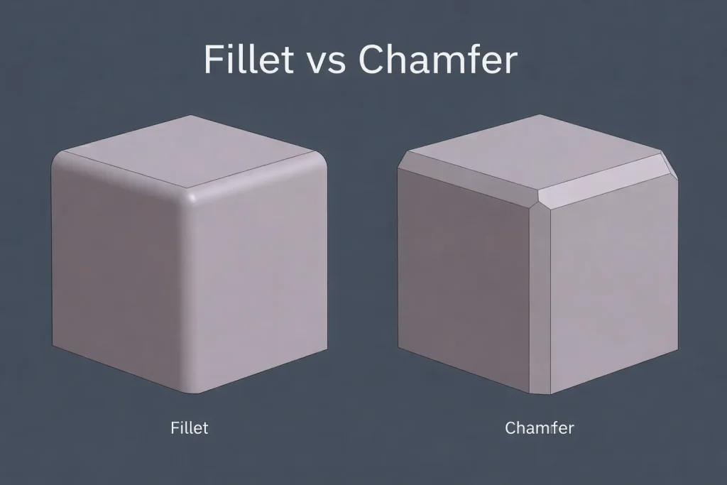
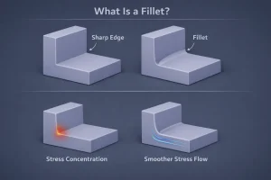
A fillet is a rounded transition between two surfaces, replacing a sharp corner with a smooth arc. On engineering drawings, these are typically specified by a radius (e.g., R0.5, R1, or R2). In CNC milling, designing internal fillets is often a manufacturing necessity rather than just a design choice, as cutting tools are inherently round. A well-designed internal fillet helps distribute stress more evenly and allows for a smooth toolpath, which is essential for ensuring structural continuity and part longevity.
What Is a Chamfer?
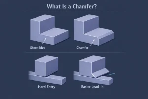
A chamfer is a flat, angled surface created by cutting away a sharp edge, most commonly at a 45-degree angle. On drawings, it is usually defined by a size and angle, such as 1 × 45° or shorthand notation like C0.5. Chamfers are common in CNC machining because they are highly practical. They are frequently used on hole entries, shaft ends, and external edges to provide a clear lead-in for assembly, effectively removing sharp edges and burrs in a single, efficient operation.
How to Choose Between Fillets and Chamfers
In machined part design, fillets and chamfers should not be treated as interchangeable features. The right choice depends on the specific function of the location and the realities of the manufacturing process.
Structural Transitions
If a specific location serves as a load-bearing transition or is subject to cyclic stress, a fillet is generally the preferred choice. The curved transition allows stress to flow more gradually through the material, minimizing the risk of localized failure compared to the abrupt geometric change of a chamfer.
Assembly Guidance
If the primary goal is to help two parts mate together, a chamfer is usually the more direct solution. The angled face acts as a lead-in, which significantly reduces alignment difficulty and prevents interference during assembly. This is why chamfers are the standard for hole entries and shaft ends.
Internal Corners
In the physical world of CNC milling, internal corners should almost always be designed with fillets. Because cutters are circular, forcing a perfectly sharp internal corner increases tool wear and can induce unwanted vibrations. Designing internal corners to match standard tool diameters ensures a more stable and efficient machining process.
Edge Cleanup
For external edges that do not carry heavy loads but need to be safe to handle, a chamfer is a simple and effective choice. It quickly removes sharp edges and burrs, improving both safety and handling without the complexity of a full-radius transition.
Visual and Tactile Feel
When appearance or user interaction is a priority, fillets generally create a softer, more continuous visual transition. Chamfers, by contrast, result in sharper, more mechanical lines. In parts where touch or aesthetic quality is important, the choice between these two can noticeably influence the final design intent.
Manufacturing Costs
In high-volume production, chamfers are often easier to standardize and can be applied to multiple edges with minimal programming changes. Fillets can sometimes be more expensive if the specified radius is non-standard, forcing the shop to use specialized or non-optimal tooling.
Differences Between Fillets and Chamfers
While both are common edge treatments, fillets and chamfers differ significantly in their engineering purpose and implementation. The following table summarizes their main differences:
| Feature | Fillet | Chamfer |
| Geometry | Rounded arc transition | Flat angled edge |
| Primary Function | Structural transition & stress reduction | Edge breaking & assembly guidance |
| Stress Behavior | Superior; ideal for high-stress areas | Good; less effective under heavy loads |
| Drawing Callout | Radius value (e.g., R1) | Size × Angle (e.g., 1 × 45°) |
| Machining Logic | Tool radius dependent | Simple path; highly standardized |
| Visual Character | Soft and continuous | Sharp and mechanical |
Structural and Stress Characteristics
From a design perspective, a fillet provides a continuous, curved transition that disperses stress away from corners. A chamfer, while better than a sharp edge, still introduces a geometric break that is less effective at mitigating stress concentrations in fatigue-sensitive applications.
Machining and Documentation
Documentation varies by feature: fillets focus on curvature (radius), while chamfers define the depth and angle of the cut. Regarding production, internal fillets are strictly bound by cutter geometry, whereas chamfers provide greater flexibility and are often more economical for standard edge-breaking across large production runs.
Applications and Aesthetics
Fillets offer a continuous, integrated aesthetic, whereas chamfers highlight clear, mechanical boundaries. Choosing between them often requires balancing structural requirements, machining constraints, and the intended design language of the part.
Design Best Practices
To optimize your design for manufacturing (DFM) and control costs, keep these points in mind:
- Match Tooling: Align internal fillet radii with common end-mill diameters to ensure efficient machining and avoid the need for custom tooling.
- Clarify Intent: Specify chamfer dimensions clearly on drawings to avoid ambiguity; do not rely on generic notes like “remove sharp edges.”
- Standardize Features: Minimize the variety of fillet and chamfer sizes on a single part. Consistency reduces tool changes and setup time, leading to higher efficiency.
- Use Explicit Callouts: Always provide specific numeric values. Clear documentation reduces back-and-forth communication and minimizes the risk of rework.
- Avoid Over-Complexity: Sometimes complex edge treatments look great in CAD but are unnecessary in production. Prioritize simple, standard features whenever they meet the structural requirements.
Conclusion
Fillets and chamfers represent a balance between engineering function and manufacturing reality. Fillets excel in handling structural loads and internal transitions, provided the design remains tool-compatible. Chamfers remain the go-to solution for efficient assembly guidance and external edge protection. For parts that require both design accuracy and consistent execution, reliable CNC machining services also play an important role in turning these edge details into practical manufacturing results. Ultimately, whether a part is easy to manufacture and performs well often comes down to how rationally these edge details are defined.