
溝加工は、CNC加工では一般的ですが、過小評価されがちなプロセスです。小さな溝加工は、シール、位置決め、潤滑、ツールリリーフ、アセンブリクリアランスなどの機能を果たすことがある。この記事では、溝加工の定義、加工プロセス、溝加工の種類、工具の選択、主要パラメータなど、いくつかの側面から溝加工の製造ロジックを説明します。
溝加工とは?
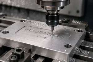
溝加工とは、特定の切削工具を使用して、被加工物の表面に一定の深さ、幅、断面形状の溝を加工するプロセスを指す。
このプロセスは主に、サークリップ溝による軸方向の位置決め、シール溝による高圧流体の漏れ防止、ジャーナル・ベアリングやガイドにオイル・トラックを形成して潤滑分布を最適化するなど、特定の機械的機能を実現するために使用される。
溝加工工程のワークフロー
標準的なCNC溝加工は、次のようなライフサイクル全体を網羅しています。 エンジニアリング・デザイン 最終的な現場での精密切断まで、溝幅と深さの正確な制御を保証します:
エンジニアリング・デザイン
シールや位置決めなどの機能要件に基づいて、溝の幾何学的断面がCAD図面で定義されます。設計段階では、溝幅の公差、深さの公差、ルートフィレット、側壁の垂直度を指定し、その後の加工に確かな基礎を提供する必要があります。
セットアップとツールアライメント
プログラムが生成されると、加工位置に基づいて適切なチャックまたは固定具が選択されます。高精度のラジアルおよびアキシャルツールアライメントが実行され、加工座標が設計図仕様と一致することを確認します。
ラフ・グルービング
幅の広い溝の場合、複数のストレートプランジや分割された切削方法を採用し、スムーズな切りくず排出を維持しながら材料を効率的に除去し、仕上げに均一な取り代を残す。
ボトム微調整
工具が溝床に到達した後、横方向のスイープまたはステアリング動作が実行され、粗加工によって残された段差が取り除かれる。
クリーニングの仕上げ
ツールは片側の側壁に沿って床まで突っ込み、水平に横切り、反対側の壁に沿って上方に引っ込む。この連続的な経路により、1回の動作で両方の側壁と床の仕上げが完了し、ツールの跡が残りません。
格納と検査
工具は安全な経路に沿って後退し、切り屑は除去される。その後、専用のゲージを使用して、溝幅、深さ、面取りを受け入れ基準に照らして検証します。
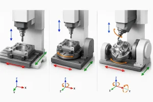
溝加工の種類
加工位置と切削ロジックに基づき、溝加工は次のようなコア・オペレーション・タイプに分類される:
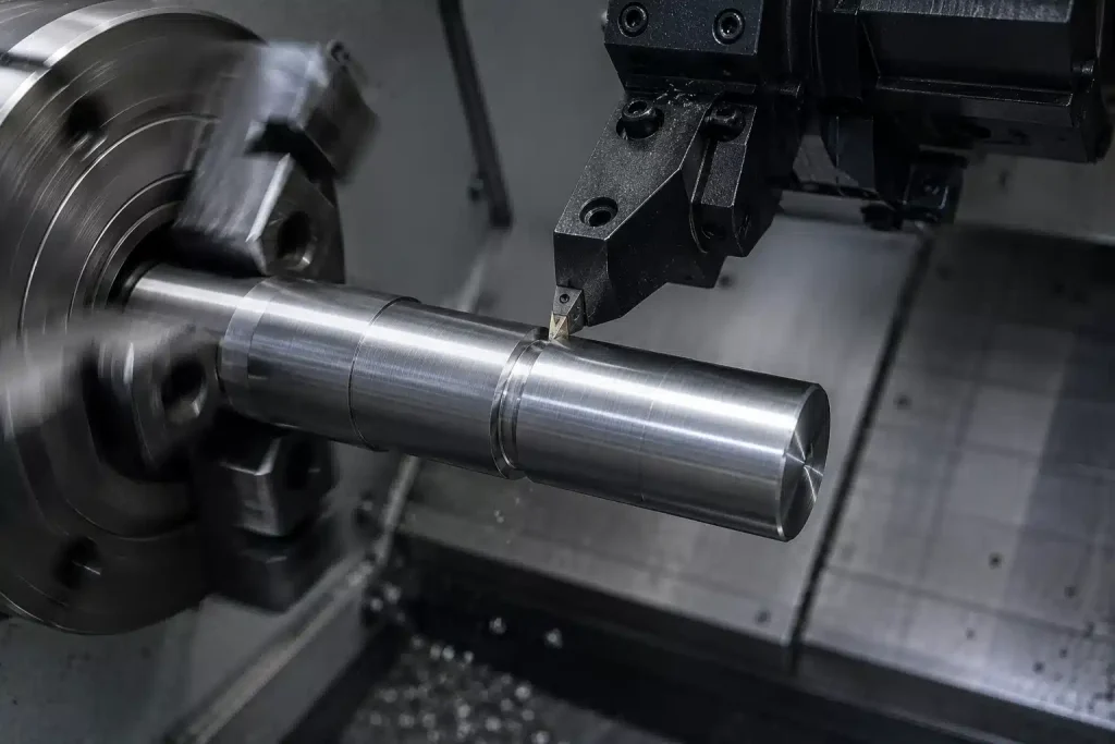
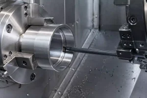
外溝加工
外面溝加工は、ラジアルプランジまたはラテラルターニングパスを使用するターニングセンターで行われる標準的な加工です。この加工の焦点は、高圧クーラント噴射による側壁仕上げとフロア平坦度の確保であり、シャフト部品のサークリップ溝やシールリングの加工に最も一般的な方法です。
内部溝加工
内面溝加工とは、ブラインドボア内で行われる切削加工を指す。 $L/D$ (長さ対直径)比が大きくなるため、通常、内部冷却を備えた専用の防振ボーリングバーや、狭いスペースでの切り屑排出の困難を克服するための段差送りや横方向のベースクリーニング経路の使用が必要となる。
フェース溝加工
切削半径は深さによって変化するため、このプロセスでは、円形加工全体を通して安定した切削力を維持するために、定面速度(CSS)制御と正確な進入角度の調整に依存しています。
リリーフ・グルービング
リリーフ溝加工は、シャフトの肩やねじの端にクリアランスを作るために行われる機能的な加工で、その目的は、加工応力を除去したり、相手部品のためのスペースを確保したりすることで、一般的には、あらかじめ定義された固定深さの経路を利用して、余分な材料を迅速かつ正確に除去する。
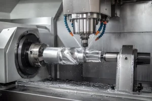
スパイラル・グルービング
螺旋溝加工は、回転運動と軸方向送りの同期補間によって実現される特殊な加工であり、技術的な難しさは、送り速度とスピンドル速度(螺旋角度)の間の正確な比率を維持することにある。
プロファイル溝加工
プロファイル溝加工は、多軸輪郭補間を使用して複雑な形状を切削するプロセスです。台形やアリ溝のような特殊な形状の場合、このプロセスでは、特殊な形状工具をCNC 3軸補間で置き換え、微細な層状の切削パスを使用して幾何学的精度を確保し、スキャロップの高さを最小限に抑えます。
溝加工に必要な工具
高品質の溝入れ加工は、高剛性切削工具、安定したワーク保持、精密測定機器の相乗効果に依存しています。
-
旋削用溝入れ工具: 献身 CNC旋盤チップブレーカーは、狭いスペースでチップを強制的にカールさせ、破損させる。
-
フライス溝加工用カッターおよびエンドミル: マシニングセンタで、回転していない部品に横方向または軸方向の送りによってさまざまな溝を切削するために使用される。
-
リジッドツールホルダー 高強度スチール製ホルダにより、極端なラジアル切削力下でも工具先端がたわんだり、びびったりすることがない。
-
防振ボーリングバー: 重金属コアまたはダンピングモジュールを装備し、長いオーバーハング内面加工時の高調波を抑制。
-
高圧クーラントシステム: 切屑を溝から押し出し、再切削を防止するため、工具に高圧流体を流す。
-
専用グルーブゲージ: 根元の直径や幅を高精度で確認するためのノギス、マイクロメーター、Go/No-Goゲージなど。
精密溝加工の主要パラメータ
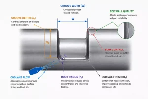
溝加工において、高精度の加工結果を得るには、いくつかのコアパラメータの正確な制御が必要です。これらの要因は、加工効率、工具寿命、切り屑排出に影響します、 溝の表面品質そして寸法安定性である。
- 切削速度 Vc: 加工効率と工具寿命を左右する。速度が速すぎると、切削温度が高くなり、刃先が盛り上がり、側壁の仕上げが損なわれます。一方、速度が遅いと、加工効率が低下し、加工硬化を引き起こす可能性があります。
- フィード・レート f: 加工リズムと切りくずの形態を決定する。適切な送り速度は、効率的な切り屑の分断と排出を保証する。そうでないと、切り屑が絡まって側壁に傷をつける可能性がある。
- デプス・オブ・カット 切削力に直接影響します。過度の深さは、スピンドル負荷を増加させ、退避経路を詰まらせ、二次切削やチップチッピングにつながる危険性がある。
- システム剛性(ツールのオーバーハング): 加工の安定性を決定する。過度のオーバーハングは高調波(びびり)を誘発し、溝底に波状のパターンが生じ、幾何公差が損なわれる。
- クーラント圧: 半密閉作業には不可欠。高圧のクーラントは切り屑を強制的に排出する主なメカニズムであり、圧力が不十分だと切り屑の堆積や表面の損傷につながる。
- ツールパス: 負荷分散を決定します。最適化されたエントリー/エグジット戦略とセグメント化されたカッティングは、ドエルマークを最小限に抑え、チップの破損につながる可能性のある急激な衝撃荷重を防ぎます。
溝加工における注意事項
プロセスの品質と生産量を確保するためには、以下のパラメーターの厳格な管理が不可欠である。
チップコントロール
溝加工は、目詰まりを起こしやすい典型的な密閉切削加工である。内径旋削加工では、切り屑を流し出し、側壁の傷を防ぐために、貫通クーラントを備えたホルダーが好まれることが多い。
ツール・オーバーハング
深い溝や内径の場合、オーバーハングと直径の比(L/D)は安全な範囲にとどめるべきで、スチール・バーでは通常L/D≦3である。長いオーバーハングが避けられない場合は、パラメーターを下げるか、減衰付きバーに変更する。
ステップオーバー距離
幅の広い溝を加工する場合は、負荷スパイクの引き金となる大きな中間段差を防ぐため、工具幅の60%から80%の段差を維持する。ドエルマークをなくすために、円弧の出入り口を使用する。
材料特性
延性の高い素材(アルミニウムや銅など) は、エッジが盛り上がる傾向がある。研磨された鋭利なチップを優先し、十分なクーラントを使用して摩擦係数を下げてください。
よくあるご質問
グルービングとスロッティングの違いは?
これらの用語は、機械製造業では異なる焦点を持っている:
- グルービング: 外径、内径、フェース溝など、回転部品の特定の幾何学的断面を、側壁仕上げと厳しい公差に重点を置いて切削することを指す。
- スロット: 一般的にフライス加工に関連する。エンドミルやサイド・アンド・フェース・カッターを使用して、非回転部品にキー溝やT溝のような直線状または囲まれた溝を切削することを指す。
なぜ溝加工では切りくず処理が重要なのか?
チップ管理はプロセスの一貫性を直接決定する:
- 避難の制限: 深くて狭い溝が切りくずの逃げ道をふさぎ、しばしば再切削につながる。
- 表面的なダメージ: 粉砕された切りくずは表面粗さを損ない、部品の不合格につながる。
- 工具の故障: 詰まりは急激な負荷スパイクを引き起こし、インサートのチッピングやバーの破損を引き起こすが、これは自動化された大量生産では致命的なリスクである。
溝加工に適した材料は?
溝入れ加工を計画する際、異なる材料が工具寿命や工程の安定性にどのような影響を与えるかを理解することは有益である:
- 快削鋼: これらの材料は一般に溝加工が容易である。というのも、短くて脆い切り屑が生成されるため、排出が容易で、狭い溝での目詰まりのリスクを軽減できるからである。
- アルミニウム合金: アルミニウム合金は切削速度が速いが、BUEとして知られるビルドアップエッジが発生しやすい。研磨された鋭いチップと十分なクーラントは、溝表面の仕上げをきれいに保つのに役立ちます。
- ステンレス鋼、特に300シリーズ: これらの材料は加工硬化を起こしやすい。実際には、局所的な硬化が工具の早期摩耗や破損につながるため、切削中に工具が滞留したり、1つの位置に留まったりしてはならない。
- チタンと超合金: これらの材料は、熱伝導性が悪く、刃先付近に熱が集中するため、溝加工が難しくなる。工具寿命を延ばし、加工を安定させるために、高圧貫通クーラントを推奨することが多い。
結論
溝加工の基本的な課題は、限られたスペースで高精度の制御を実現することにある。CNCによる大量生産では、やみくもに均一な切削パラメータを採用すると、工具の不具合や表面の損傷が頻繁に発生します。材料特性を深く分析し、論理的な切削経路を設計し、正しいチップブレーキング・ソリューションを適合させることによってのみ、製造業者は厳しい密閉性と位置決め要求の下で、高品質の出力を確保することができる。