
薄肉部品はCNC加工では一般的ですが、標準的な部品よりも慎重な工程計画とワーク保持が必要です。薄肉で構造剛性が低いため、これらの部品は切削荷重、クランプ条件、加工中の振動の影響を受けやすくなります。
これらの構造は、航空宇宙、自動車、電子機器、ハウジング、スリーブ、軽量ブラケットなどによく見られる。加工順序や治具サポートが適切に計画されていない場合、切削パラメータを下げるだけでは、一貫した結果を得るには不十分な場合があります。
この記事では、薄肉加工の基本コンセプト、一般的な加工上の課題、部品管理と加工品質を向上させる実践的な方法について解説する。
薄肉加工とは?
薄肉加工とは、断面が薄い、壁が支持されていない、または構造剛性が低い部品をCNCで加工することを指す。単一の加工方法ではなく、フライス加工、旋盤加工、ドリル加工、ボーリング加工、タッピング加工、仕上げ加工に現れる可能性のある加工条件である。
部品が薄肉とみなされるかどうかは、肉厚だけでは判断できません。また、部品全体の大きさ、壁の高さ、ポケットの深さ、支持されていない長さ、公差要件によっても異なります。例えば、小さくて浅い部品であれば2mmの肉厚でも比較的加工しやすいかもしれませんが、深いアルミ製ハウジングでは同じ肉厚でも加工リスクがはるかに高くなります。
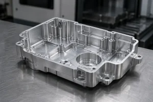
薄肉部品は、アルミニウム、ステンレス鋼、チタン、プラスチック、その他のエンジニアリング材料から加工できます。CNC加工では、薄肉 アルミ部品 アルミニウムは軽量ハウジング、ブラケット、スリーブ、フレーム、電子筐体などに広く使用されているため、特に一般的です。
薄肉加工における一般的な課題
薄肉加工は通常、薄い部分が切削、クランプ、材料除去の際にサポートを失うと困難になります。以下の課題は、部品の精度、表面品質、再現性に影響する最も一般的な問題です。
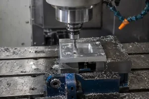
加工中の変形
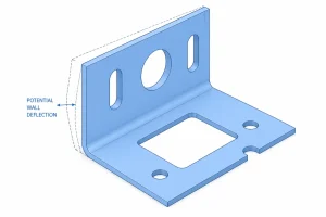
変形は薄肉加工における最も一般的な問題の一つである。切削工具が材料を除去する際、ワークピースに横方向の力が加わります。壁が薄かったり、サポートが不十分だったりすると、切削中に壁がわずかにたわみ、寸法誤差が生じることがあります。
この問題は、ポケットが深く、サイドウォールが高いほど顕著になる、 大型材料除去 部分や底の薄い部分。加工中は問題ないように見えても、工具が表面から離れたり、部品が固定具から外れたりすると、薄肉部がはね返り、組立寸法や肉厚の整合性に影響を及ぼすことがあります。
クランプ歪み
薄肉部品は信頼性の高いワークホールディングを必要としますが、クランプ力自体も歪みの原因となります。パーツを強くクランプしすぎると、加工を始める前に変形してしまうことがあります。クランプが軽すぎると、切削中にパーツが動いたり振動したりすることがあります。
このため、ハウジング、スリーブ、薄板、フレーム状の部品では、クランプ力と支持位置が特に重要になります。課題は、弱い薄肉部分に過度の局所的な圧力をかけることなく、部品をしっかりと保持することです。
振動とチャタリング
特に、工具のオーバーハングが長い場合、壁の高さが大きい場合、側壁が薄い場合、固定具のサポートが不十分な場合、薄肉構造は振動を増幅する可能性がある。
振動は表面品質に直接影響し、目に見えるツールマークやびびり跡を残します。また、公差の制御も難しくなります。ひどい場合には、振動が工具の摩耗を早めたり、薄いエッジに沿ってバリや局所的な変形を生じさせたりすることもあります。
残留応力と材料の動き
板材、棒材、押出材、鋳造材から大量の材料を取り除くと、材料内部の残留応力が解放されることがあります。肉厚の薄い部品の場合、残された構造体の剛性が低いため、この動きが目立ちやすくなります。
例えば、大面積プレート ミーリングまた、深いハウジング加工や薄肉長尺部品では、加工中または加工後に反りや曲がり、寸法ずれが発生する可能性があります。材料の状態、在庫形状、加工順序はすべて、このリスクに影響する。
公差と表面仕上げ制御
薄肉部品は通常、寸法、公差、表面仕上げの点で制御が難しい。切削力、クランプ圧力、振動、材料応力はすべて最終結果に影響します。
小さなツールマーク、バリ、エッジの欠陥は、部品に機能面、外観面、穴、組み立ての特徴がある場合に、より重要になることがある。薄肉部品の場合、公差は図面からだけ評価するのではなく、部品の形状や実際の加工挙動と照らし合わせる必要があります。
薄肉加工の戦略と最適化のヒント
薄肉加工は、切削パラメータを下げるだけでは改善できない。主軸回転数、送り速度、切り込み深さは全て加工に影響するが、ワークの保持方法、支持構造、加工順序が適切でない場合、パラメータを下げても変形や振動の問題を解決できないことがある。
より良いアプローチは、ワーク保持、切削力、ツールパス戦略、材料除去順序、仕上げ代など、いくつかの側面から同時にプロセスを制御することである。その目的は、薄い部分が早期に支持力を失うのを防ぐことである。
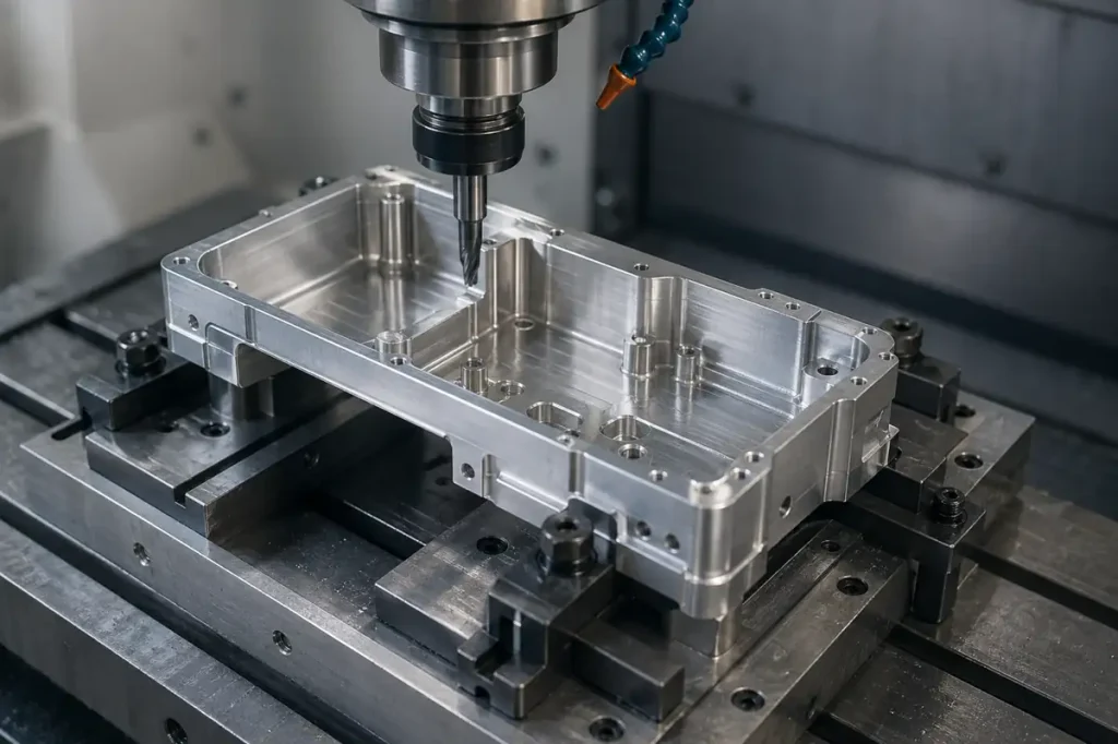
ワーク保持とサポート安定性の向上
ワーク把持は、薄肉加工で最初に解決すべき問題のひとつです。部品は切削力に対抗するために十分なサポートが必要ですが、過度のクランプ圧力は加工が始まる前に歪んでしまう可能性があります。
このため、できるだけきつくクランプすることが目標ではない。その代わり、サポートは均等で、うまく分散させる必要があります。部品の形状によっては、ソフトジョー、カスタム固定具、バックサポート、位置決めピン、補助クランプ構造などを使用して、局所的な変形を抑えることができます。
ハウジング、薄板、スリーブ、フレーム状の部品では、クランプ力だけでなく、サポート位置が重要になることがよくあります。適切なサポートは、局所的な剛性を向上させ、加工中の移動、振動、スプリングバックの防止に役立ちます。
材料を徐々に取り除く
薄い壁をあまり早く最終的なサイズにするのではなく、段階を追って材料を取り除くべきである。最初に材料を除去しすぎると、仕上げが始まる前に薄い部分が支えられなくなる可能性がある。
より確実な方法は、プロセスを次のように分けることだ。 粗造り荒仕上げ、中仕上げ、仕上げ。荒仕上げは、十分なサポートを残しながら、主な取り代を取り除きます。半仕上げは、部品を最終形状に近づけます。仕上げ加工は、重要な薄肉面や組立寸法を管理するために行われます。
深いポケット、背の高い側壁、大きなポケット構造の場合、主加工が完了するまで仮支持や加工代を残すことがある。こうすることで、機械加工の途中で部品がサポートされなくなるリスクを減らすことができます。
制御切削力
薄肉加工における変形や振動の問題の多くは、過大な切削力に起因する。壁にかかる側圧が大きいほど、薄肉部はたわみやすくなります。
切削力は、鋭利な工具の使用、工具のオーバーハングの低減、切り込み深さと切り込み幅の制御、急激な重切削の回避、複数回の軽いパスの使用など、いくつかの方法で制御することができる。肉厚の薄いアルミニウム部品では、切れ味の鋭い工具と安定した切りくず排出が特に重要です。
切削力をコントロールするということは、やみくもに効率を下げるということではありません。重要なのは、切削負荷を予測可能な状態に保ち、局所的な急激な力の増加を避けることです。
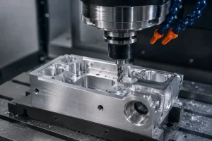
ツールパスと加工シーケンスの最適化
ツールパスと加工順序は、薄肉部品に大きな影響を与えます。適切な加工順序は、加工中のパーツの支持力を高め、歪みのリスクを低減します。
一般的には、安定したデータムを最初に確立し、剛性の高い部分を次に加工し、薄肉部分は後の作業にまわした方がよい。重要な寸法や肉薄の表面は、通常、部品がより制御された状態にあるときに仕上げるべきである。対称的な構造の場合、バランスよく材料を除去することで、不均一な応力解放を抑えることができる。
深いポケットやハウジングタイプの部品の場合、一般的なアプローチは、最初に内部荒加工を行い、次に中仕上げを行い、最後に側壁、穴、組立面を仕上げるというものです。こうすることで、加工工程全体を通して部品の挙動をより予測しやすくすることができます。
フィニッシュパスの計画は慎重に
薄肉部品の仕上げは、表面品質の向上だけではない。仕上げ加工時の切削力や、残存組織の状態も考慮する必要がある。仕上げ代が大きすぎると、最終パスでも薄肉部を押してしまう可能性があります。仕上げ代が小さすぎると、以前の加工で残った誤差やツールマークを除去できない可能性があります。
このため、仕上げ代は慎重に計画する必要がある。薄肉部は通常、軽い切削負荷、安定したツールパス、制御された仕上げパスが有効である。重要なサーフェス、穴、アセンブリのフィーチャーは、部品がまだ十分な支持力を持っているうちに仕上げる必要があります。
後にアルマイト処理、ビーズブラスト、ブラッシング、その他の表面処理が必要になる部品の場合、仕上げ加工ではエッジの状態、バリの抑制、外観上の表面保護も考慮する必要があります。これは、後処理によって機械加工の欠陥が目立ちやすくなるのを防ぐのに役立ちます。
薄肉部品の加工後の考慮事項
肉厚の薄い部品は、機械加工後も慎重な取り扱いが必要です。部品を治具から離すこと、バリを取り除くこと、主要寸法を検査すること、表面仕上げの準備をすることは、すべて最終結果に影響します。
アンクランプ後の部品のチェック
肉厚の薄い部品は、冶具に固定されている間は許容範囲内に見えるかもしれませんが、アンクランプ後に最終的な状態をチェックする必要があります。クランプ圧を取り除くと、スプリングバック、わずかな反り、寸法ドリフトが現れることがあります。
ハウジング、スリーブ、薄い板、ポケットの深い部品については、平坦度、真円度、肉厚の均一性、穴の位置、解放状態での組立面をチェックすることが有効である。変化が顕著な場合は、加工順序、治具のサポート、材料の状態などを見直す必要があるかもしれない。
バリやエッジダメージの抑制
バリ取りの際、薄いエッジはより敏感です。過度のサンディング、面取り、手作業によるエッジ処理は、エッジの寸法を変えたり、化粧面を傷つけることがあります。
バリ取りは、特に穴、薄い開口部、シーリング・エッジ、および目に見える表面の周囲で、管理され、一貫性がなければならない。組み立てやシーリングが必要な部品については、生産前にエッジの状態を確認する必要がある。
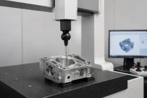
重要な寸法の再点検
薄肉部品は機械加工や取り扱いの後に動く可能性があるため、重要な寸法は最終的に自由な状態でチェックする必要がある。重要な特徴には、組立穴、シール面、位置決め面、平面度、真円度、肉厚などがある。
公差の厳しい部品の場合、工程内測定だけでは不十分な場合がある。最終検査では、可能な限り、その部品がどのように使用されるか、またはどのように組み立てられるかを反映させるべきである。
表面仕上げのための入念な準備
多くの薄肉アルミニウム部品は、陽極酸化処理、ビーズブラスト、ブラッシング、その他の表面処理を必要とします。小さな機械加工跡、バリ、傷、エッジの欠陥は、仕上げ後に目立ちやすくなることがあります。
表面処理の前に、外観面、穴のエッジ、薄肉エッジ、機能面をチェックすべきである。部品に外観の要求がある場合、機械加工と仕上げ加工は別々の問題として扱うのではなく、同じ品質要求に従うべきである。
取り扱いと梱包時の薄い切片の保護
また、薄い部分は、取り扱い、積み重ね、輸送中に損傷することがあります。長い側壁、薄いエッジ、開いたフレーム、薄い底部などは、正しく支持されていないと、曲がったり跡がついたりすることがあります。
このような部品の場合、薄い壁に直接圧力がかからないようにしてください。セパレーター、ソフトパッド、特注トレイ、保護パッケージなどが、重要な表面や薄い部分を安全に保つために必要な場合があります。
結論
薄肉加工は、薄い部分から材料を除去するだけではありません。主な課題は、切削力、クランプ圧力、振動、材料の移動が残りの構造に影響を与える一方で、部品を制御し続けることです。
薄肉加工を成功させるには、通常、適切なワーク保持、緩やかな材料除去、制御された切削力、計画されたツールパス、入念な仕上げ加工、加工後の検査が必要です。肉厚、ポケットの深さ、サポート機能、公差要件などの設計上の選択も、部品を安定して加工できるかどうかに影響します。
お客様の部品に薄い壁、深いポケット、大きな材料除去、または厳しい公差の特徴がある場合、Minhe CNCはお客様の図面を確認し、形状、材料、公差、および表面仕上げの要件に基づいて、実用的なCNC加工アプローチを提案することができます。