

Geometric dimensioning and tolerancing, usually shortened to GD&T, is a symbolic language for defining geometry on engineering drawings. It covers more than size, spelling out the allowable form, orientation, location, and runout of each feature so a designer, a machinist, and an inspector read the same requirement.
Conventional plus/minus dimensions leave real geometry open to interpretation. Two holes can each pass a size check and still sit too far apart to assemble. GD&T removes that ambiguity by tying each tolerance to the function the feature must perform.
The system rests on ASME Y14.5, whose current edition dates to 2018, and on the ISO GPS family led by ISO 1101. Both share the same core symbols, so a callout means the same thing at suppliers in different countries.
This guide explains the five tolerance families and their symbols, feature control frames, datums, modifiers, and the mistakes that raise cost.
What Is GD&T?
Size dimensions tell only part of the story. A callout states how far a surface may deviate from ideal form, how a feature may tilt relative to a datum, or how far a position may shift. The tolerance zone comes from function, not from a generic drawing number.
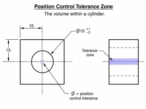
Every callout creates a tolerance zone the feature must stay inside. Its shape is part of the symbol meaning: cylindrical under position for a hole axis, two parallel planes under flatness, or a curved band under profile of a surface.
Geometric control splits into five families: form, orientation, location, profile, and runout. Material condition modifiers then adjust tolerance as feature size changes, and each family below is explained with the symbols it uses.
Why Is GD&T Important?
Each callout defines its own measurement: what to check, against which datum, and inside which zone. Quoting, machining, and inspection teams then read the same part without a phone call.
Because every tolerance is tied to function, tolerances can be opened where assembly allows. Looser values mean faster feeds, fewer setups, and less scrap, which is where GD&T pays for itself without hurting fit.
Used consistently, GD&T cuts scrap and makes inspection results repeatable. That is why automotive, aerospace, and medical device companies treat it as standard practice on engineering drawings.
It pays off most when fits are critical, when several suppliers quote the same part, or when a drawing will be read years later. One-off parts with no mating features rarely need it.
Types of Geometric Tolerances
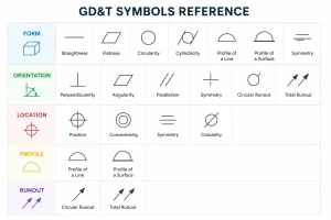
Geometric tolerances are written with 14 standard symbols grouped into five families: form, orientation, location, profile, and runout. The count breaks down as four form, three orientation, three location, two profile, and two runout symbols. Each family controls a different kind of variation, so the type should follow what your part must do in the assembly.
Form Tolerances
Form tolerances control the shape of a single feature and need no datum. Straightness keeps an axis or an edge inside a narrow zone, flatness keeps a sealing surface planar, and circularity or cylindricity limit how far a cylinder departs from a true circle.
Orientation Tolerances
Orientation tolerances relate a feature to a datum. Perpendicularity keeps a bore square to a mounting face, parallelism keeps two machined surfaces level, and angularity controls a specified angle. Use them whenever assembly depends on the angle between two features.
Location Tolerances
Location tolerances define where a feature sits. Position is the most common and handles hole patterns, slots, and bosses. Concentricity and symmetry cover coaxial or symmetrical relationships but are harder to inspect and often lose to a tighter position callout.
Profile Tolerances
Profile tolerances govern line or surface contours. A surface profile can manage form, orientation, location, and size in one callout, which makes it the most versatile tool for complex free-form geometry such as turbine blades, impellers, and cast housings.
Runout Tolerances
Runout tolerances limit variation on rotating features. Circular runout checks each cross-section; total runout checks the whole surface at once. Both appear on shaft journals, bearing seats, and pulleys to control vibration and wear.
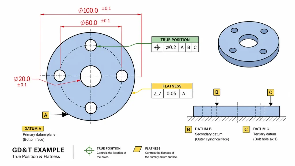
Types combine on a real part. A housing may carry position for a hole pattern, perpendicularity tying the pattern to a datum face, and flatness on the datum face itself. Stacked frames keep these relationships readable in one place.
When the function on your drawing is unclear, tightening a conventional dimension is rarely the fix. State the functional requirement first, then choose the tolerance that measures it.
Choose by function, not habit. Position and profile cover most locating tasks, runout covers rotation, and form covers sealing surfaces. Cost follows the number: tighter values mean slower feeds, more setups, and more scrap, so pick the loosest zone that still guarantees assembly and review it with the machinist before quoting.
Feature Control Frames
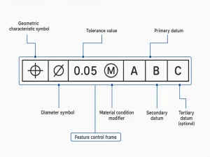
A feature control frame is the rectangular box that carries a geometric tolerance. Read left to right: symbol, tolerance value, any modifiers, then the datum references that set up measurement. A leader line points the frame to the feature it controls.
Anatomy of a Feature Control Frame
A typical frame reads as position, 0.05 at maximum material condition, referenced to datums A and B. The box keeps the whole requirement in one readable place; frames do not replace conventional dimensions, they control the geometry that dimensions alone cannot express.
Stacked Frames
When one feature needs several controls, stack the frames. A hole can carry position relative to A and B in one frame and perpendicularity to the datum face in another. Both are checked from the same datum setup.
Basic Dimensions
Basic dimensions define the exact geometry a frame manages. They sit in a box and carry no tolerance of their own; the frame supplies it.
What a Frame Controls
A frame can control a surface or an axis. A leader to the surface means the surface must lie in the zone; a frame under a dimension controls the derived axis or center plane. A diameter symbol in the tolerance compartment makes the zone cylindrical, as with position of a hole.
Keep frames readable: one characteristic per frame, one zone per callout, and datum letters that exist on the drawing. Complicated frames are a common source of inspection disputes.
Datums and Datum Reference Frames
Datums are the physical features that set up the reference system. A datum reference frame uses three mutually perpendicular planes, usually A, B, and C, so every measured feature shares one origin.
Datum Features and the Reference Frame
A datum is theoretical; the datum feature is the actual surface that contacts it. The simulated plane touches the high points of the feature, which is why flat, rigid surfaces make reliable datums.
Datum Order
Letter order matters. The primary datum carries the most influence; the secondary restrains the next direction; the tertiary locks the remaining rotation. Change the order and the part sits differently in the fixture, which changes what the inspector measures.
Choosing Datum Features
Good datum features are stable, machinable, and measurable. A large flat face beats a short edge as a primary datum because your part rests on it reliably and the setup repeats; a small or soft feature chosen as a datum is a common source of disputes between the shop and the designer.
Simulated Datums
Simulated datums reproduce the planes physically. A surface plate stands in for a primary plane, a chuck axis for a datum axis, and precision parallels for secondary planes, so the letters connect directly to the inspection setup.
Round parts often use a datum axis from a turned diameter or chuck. The axis controls location and rotation better than a narrow edge can.
Material Condition Modifiers
Material condition modifiers adjust tolerance as feature size changes. Under maximum material condition, the tolerance grows when a hole or shaft departs from its largest material size, so a hole pattern with position at MMC accepts more parts without changing assembly. That is why MMC is standard on clearance holes.
MMC and Bonus Tolerance
Bonus tolerance is the extra allowance gained as a hole grows or a pin shrinks. Applied at MMC it raises yield without changing the worst-case assembly.
Least Material Condition and RFS
Least material condition protects minimum wall thickness and edge distance. Regardless of feature size applies no adjustment at any size.
Choosing the Modifier
Pick MMC when clearance at assembly drives the design, LMC when a minimum wall or edge distance must survive, and RFS only when the relationship must hold at every size.
The choice of modifier often affects cost and yield more than the number in the frame. Confirm the condition with your machinist before quoting.
GD&T in Practice
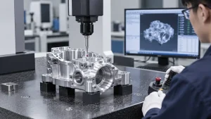
GD&T earns its place when your parts must assemble and interchange. Design teams apply it during engineering fit selection, and inspectors verify callouts with gages or coordinate measuring machines against the same datum frame.
Typical applications include:
- Automotive engine and transmission parts that must fit in tight assembly envelopes.
- Aerospace components where position and orientation affect safety-critical functions.
- Medical devices that need consistent fit across production batches.
- Machined housings and fixtures where datums decide how faces relate.
- Shafts, gears, and bearings where runout limits vibration and wear.
- Valve bodies and pumps where sealing faces must stay flat and square.
Gages verify fast and suit production runs: a functional gage checks position at MMC in one pass. A CMM handles complex profiles and multiple datums at the price of longer programming, and optical scanners help where free-form surfaces make physical gages impractical. Whichever method you choose, the datum order on the print has to match the setup.
Lock the tolerance strategy before the CAM program and fixtures are set. Tool paths, workholding, and measurement all depend on how the part is held.
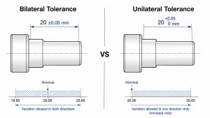
The choice between bilateral and unilateral tolerance affects how the shop aims the process and what it costs.
Common GD&T Mistakes
Most problems come from over-tolerancing, not under-tolerancing. Before you add a geometric callout, ask which failure it prevents; applying controls to every feature raises inspection cost without adding function.
The mistakes below account for most failed implementations:
- Over-tolerancing features that only need a conventional dimension, which adds inspection cost and rejects parts that would assemble perfectly.
- Choosing unstable or hard-to-measure features as datums, which makes every downstream callout unreliable.
- Ignoring material condition modifiers when clearance depends on feature size, which throws away bonus tolerance and raises scrap.
- Mixing ASME and ISO conventions on one drawing, which sends conflicting messages to suppliers working to a different standard.
Tighter values are not always better. A position tolerance of 0.05 costs more to hold than 0.2 on most machines, and that cost is justified only when assembly or performance demands it.
Review each callout on your drawing for cost impact as part of design for manufacturability. A machining partner can flag values that force slow setups or special tooling.
A drawing standard helps: name the default modifier, the datum lettering rule, and the convention for stacked frames. Engineers, machinists, and inspectors then resolve the same question the same way.
Done well, GD&T cuts scrap, shortens inspection, and makes supplier quotes comparable. Done poorly, it adds cost. The difference is whether each callout ties to a function, a stable datum, and a realistic inspection plan.
MinHe – CNC Machining Manufacturer
GD&T callouts are only as good as the part that receives them. Send your drawing with the required tolerances to our engineers, and the machining process and inspection plan can be reviewed before production starts.
Confirming the setup at the quoting stage is far cheaper than reworking a batch after machining. That is where GD&T pays back in lower scrap, faster delivery, and fewer drawing disputes.