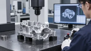


A coordinate measuring machine, commonly abbreviated as CMM, is a measuring device used for dimensional and geometric inspection. It collects three-dimensional coordinate data from a part surface to calculate lengths, hole diameters, hole positions, planes, cylinders, profiles, and the positional relationships between different features.
The importance of a CMM lies in its ability to evaluate several related features within the same coordinate system. For parts with multiple datums, complex hole patterns, or geometric tolerance requirements, calipers, micrometers, and plug gauges alone may not provide enough information to verify how those features relate to one another.
However, a CMM is not suitable for every inspection task. Its practical capability depends on the machine type, measuring range, probe configuration, part geometry, and operating environment. This article explains the main types, components, working process, basic operation, advantages, and limitations of coordinate measuring machines.
What Is a Coordinate Measuring Machine?
CMM stands for Coordinate Measuring Machine. The machine collects measurement points from a part surface along the X, Y, and Z axes and uses measurement software to calculate dimensions, shapes, orientations, and positional relationships.
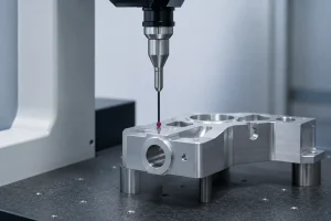
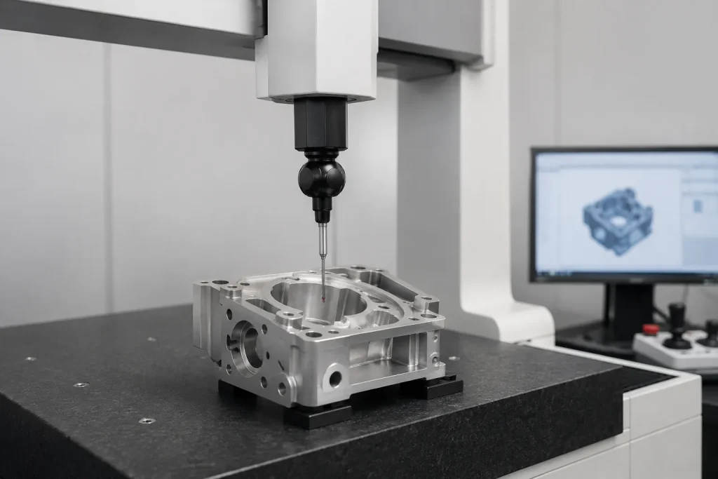
During measurement, a probe touches or scans the part surface while the machine records the position of each point in a three-dimensional coordinate system. The software then uses these coordinates to construct planes, circles, cylinders, spheres, lines, or surfaces and compares the actual results with engineering drawings or CAD models.
For example, when inspecting a machined housing, a CMM can measure more than the hole diameter. It can also evaluate:
- Center-to-center distances between holes
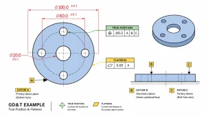
- Hole position relative to a datum surface
- Flatness of a mounting face
- Perpendicularity between two surfaces
- Positional relationships between two bearing bores
- Deviation between the actual profile and the CAD model
A CMM therefore does more than measure individual dimensions. It can also analyze the geometric relationships between several features within a common coordinate system.
CMMs are commonly used to verify part dimensions, geometric tolerances, and feature locations against engineering drawings or CAD models. They may also support first article inspection, tooling verification, and dimensional reporting.
How Does a Coordinate Measuring Machine Work?
The basic CMM process includes part positioning, coordinate system alignment, point collection, geometric calculation, and result output.
Before measurement, the part is placed securely on the table. A coordinate system is then established using datum planes, datum holes, or centerlines specified on the drawing. This coordinate system determines the reference direction for subsequent dimensional and geometric tolerance calculations.
The probe then follows a defined path to touch or scan the part surface. The machine records the X, Y, and Z coordinates of each measurement point and sends the data to the measurement software.
Different features require different point distributions. A plane requires points across several areas, a circular hole requires points around its circumference, a cylinder requires measurements at different heights, and a freeform surface may require continuous scanning.
The software uses these points to create geometric elements and calculate their actual dimensions, orientation, and position. The results can then be compared with drawing dimensions, tolerance limits, or CAD models. A report may show the nominal value, actual value, deviation, and pass or fail status.
Main Types of Coordinate Measuring Machines
Coordinate measuring machines are generally classified according to their frame structure and method of use. Different types vary in measuring range, part-loading method, and suitable applications.
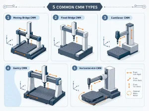
Bridge CMM
A bridge CMM has a bridge structure that spans the measuring table and moves along the table. It is one of the most common types used in quality laboratories and precision part inspection.
It is suitable for small and medium-sized parts, including housings, brackets, flanges, valve bodies, and mold inserts. Bridge CMMs offer good general-purpose capability, but the measurable part size is limited by the bridge height and table area.
Gantry CMM
A gantry CMM provides a larger measuring volume and is generally used for large or heavy parts, such as large molds, machine-tool components, aerospace structures, and large castings.
This type can accommodate larger workpieces, but it requires more installation space and greater control over the machine foundation, temperature, and surrounding environment.
Horizontal-Arm CMM
A horizontal-arm CMM approaches the workpiece from the side and is suitable for wide, thin-walled, or side-feature-intensive parts.
Common inspection targets include automotive bodies, sheet-metal panels, welded frames, large housings, and assembly fixtures. Its open structure provides good access to large side surfaces, although some small, high-precision features may be better suited to a bridge CMM.
Cantilever CMM
A cantilever CMM is supported from one side, leaving the measuring area relatively open and making parts easier to load and unload.
It is suitable for small and medium-sized workpieces, shop-floor inspection, and applications that require frequent part changes. Because the structure is supported from one side, its rigidity and measuring range depend on the specific machine design.
Portable Measuring Arm
A portable measuring arm can be moved to the workpiece, so large parts do not have to be transported to a fixed measuring table.
It is often used for on-site inspection of large workpieces, tooling verification, assembly inspection, maintenance work, and reverse engineering. Portable systems are flexible, but their results are more sensitive to operator technique, equipment setup, ambient temperature, and vibration.
Main Components of a Coordinate Measuring Machine
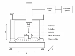
Different CMM types vary in structure, but they generally include a probe, measuring table, fixture, measurement software, and machine motion system.
Probe
The probe touches or scans the part surface and is the direct measuring element used to collect coordinate data.
Common probe systems include:
- Touch-trigger probes
- Scanning probes
- Optical probes
- Laser scanning systems
A touch-trigger probe records individual points when it contacts the surface and is suitable for holes, planes, and standard geometric features. A scanning probe collects data continuously and is better suited to cylinders, profiles, and freeform surfaces.
The stylus ball diameter, length, and angle also affect measurement capability. A large stylus ball may not enter a small hole, a long stylus may deflect, and an unsuitable approach direction may restrict access to deep grooves or internal features.
Granite Table
The measuring table supports the part and inspection fixture. Many fixed CMMs use granite tables because granite offers good dimensional stability and wear resistance.
The table size and load capacity limit the dimensions and weight of the parts that can be inspected. Chips, oil, and dust should be removed before measurement to prevent unstable positioning or part tilt.
Fixture
A fixture stabilizes the part and prevents movement during probe contact or scanning.
A suitable inspection fixture should:
- Support the part securely
- Keep the probe path accessible
- Avoid excessive clamping force
- Minimize deformation of thin-walled parts
- Maintain a consistent loading position
Although the fixture may not be part of the machine itself, it directly affects measurement repeatability.
Measurement Software
Measurement software processes coordinate data and generates inspection results. Common functions include:
- Establishing the part coordinate system
- Defining the measurement path
- Calculating geometric features
- Evaluating dimensions and geometric tolerances
- Comparing results with CAD models
- Generating inspection reports
- Storing historical measurement data
The ability to evaluate complex dimensions depends not only on the machine hardware, but also on datum selection, point distribution, and software settings.
Air System and Motion Mechanism
A CMM moves the probe along the X, Y, and Z axes. The motion mechanism generally includes guideways, drive systems, position-feedback devices, and bearing structures.
Some machines use air bearings to reduce motion resistance and therefore require a stable compressed-air supply and suitable air-drying equipment. Not every CMM uses the same design, and the actual configuration depends on the machine type.
How Is a Coordinate Measuring Machine Used?
Operating procedures vary between machines and software platforms, but the basic workflow is generally similar.
Check the Environment and Part Condition
Before measurement, the part and measuring table should be cleaned to remove chips, burrs, oil, coolant, and dust.
A part taken directly from a machine tool may still contain machining heat. For parts with tight tolerances, the workpiece should be allowed to reach a relatively stable temperature in the inspection environment.
Set Up and Calibrate the Machine
The probe ball, stylus length, and approach direction should be selected according to the part features. When the probe, extension, or probe angle is changed, recalibration is generally required.
The operator should also confirm the machine condition, measuring range, and motion path to prevent collisions between the probe, part, and fixture.
Establish the Part Coordinate System
The coordinate system should be established according to the datum requirements on the engineering drawing. A common method is to use one plane to define the primary orientation and then use an edge, hole, or shaft to define rotation and the coordinate origin.
If the coordinate system is incorrect, measurements such as hole position, position tolerance, parallelism, and perpendicularity may also be referenced incorrectly.
Run the Measurement Program
The measurement program defines the inspected features, number of measurement points, probe approach direction, and calculation method.
An automatic CMM can repeat the programmed path, while a manual machine requires the operator to control probe movement.
Review the Measurement Results
When a result appears out of tolerance, the part should not be rejected immediately. The operator should first check:
- Whether the part moved
- Whether burrs remain on the surface
- Whether the probe was calibrated correctly
- Whether the coordinate system was established correctly
- Whether the tolerance was entered correctly
- Whether the number and distribution of measurement points were suitable
- Whether the part temperature was stable
A high-accuracy machine does not automatically guarantee that every measurement result is reliable.
Advantages and Limitations of Coordinate Measuring Machines
Advantages
A coordinate measuring machine can inspect parts with complex geometry, numerous features, and complicated datum relationships.
Common advantages include:
- Measurement of various geometric features
- Evaluation of positional relationships between features
- Support for certain geometric tolerance requirements
- Generation of digital inspection reports
- Repeatable automatic measurement programs
- Comparison with CAD models
- Storage and tracking of historical measurement data
Limitations
CMMs also have limitations related to equipment cost, inspection efficiency, and operating conditions.
Common limitations include:
- Higher costs for the machine, software, and probes
- The need for regular calibration and maintenance
- Longer inspection times for complex parts
- Sensitivity to temperature, vibration, and cleanliness
- Limited access to deep grooves, narrow holes, and obstructed features
- Possible probe-force effects on thin-walled or soft parts
- Possible influence of surface reflectivity and transparency on non-contact measurement
- Dependence on correct datums, fixtures, probes, and program settings
For simple dimensions or high-throughput inspection, calipers, micrometers, plug gauges, and dedicated gauges may sometimes be more efficient.
Conclusion
A coordinate measuring machine collects coordinate data from a part surface along the X, Y, and Z axes and uses measurement software to calculate dimensions, shapes, orientations, and positional relationships. Bridge, gantry, horizontal-arm, cantilever, and portable CMMs are suited to different part sizes, inspection spaces, and operating conditions.
CMMs are commonly used to inspect automotive components, aerospace structures, precision-machined parts, molds, fixtures, and assembly tooling. They can support complex dimensional inspection, geometric tolerance evaluation, first article inspection, production sampling, and tooling verification. However, measurement reliability still depends on the probe configuration, part fixturing, datum alignment, environmental conditions, and measurement program.
For parts with simple dimensions and high inspection volumes, conventional measuring tools or dedicated gauges may be more efficient. For parts with complex geometry, multiple datums, or digital reporting requirements, a CMM can provide a more systematic set of three-dimensional measurement data.