

A transition fit is an engineering fit in which the tolerance zones of the hole and the shaft overlap. Depending on where the actual dimensions land within their tolerance ranges, the assembled parts may end up with a small clearance or a slight interference. Engineers use transition fits when they need precise location without the assembly difficulty of a full interference fit. This guide explains how fits are defined, where transition fits sit among the three fit types, when to use them, and how to specify them with ISO codes such as H7/k6.
What Is an Engineering Fit?
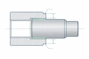
An engineering fit defines the dimensional relationship between two mating features, typically a hole and a shaft. The chosen fit controls assembly force, relative movement, positioning accuracy, load transfer, and service life. An incorrect fit can cause excessive clearance, unwanted movement, assembly difficulty, internal stress, or premature wear. Fits also determine interchangeability: parts made in different batches or by different suppliers must assemble correctly without selective fitting, which is why fits are specified on the drawing as part of the tolerance system rather than left to the machinist. Fits fall into three categories based on the relative positions of the hole and shaft tolerance zones: clearance, transition, and interference.
The Three Types of Engineering Fits
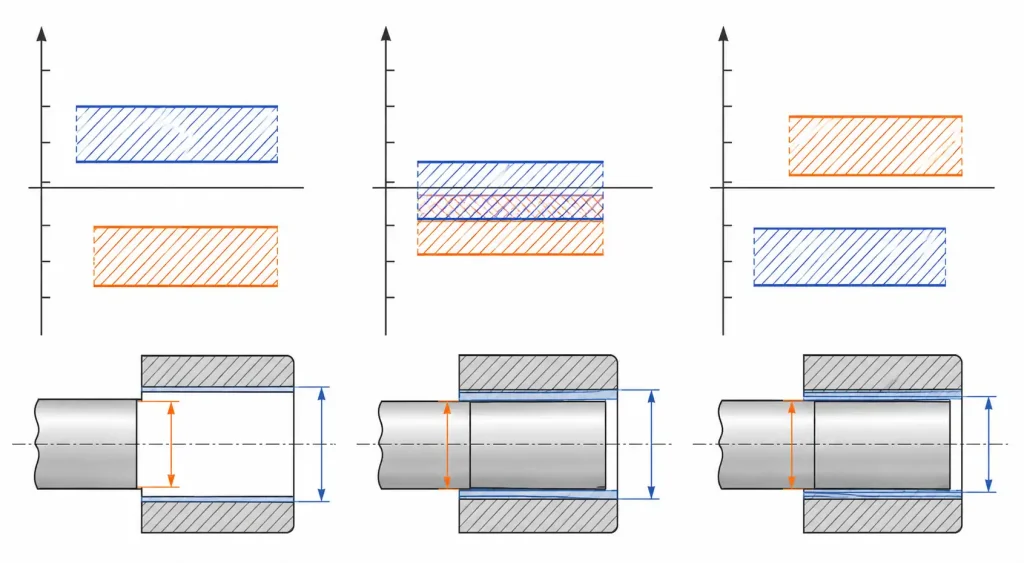
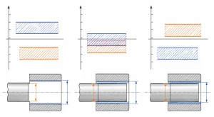
The classification of a fit depends on whether the hole tolerance zone sits entirely above the shaft zone (clearance), overlaps it (transition), or sits entirely below it (interference). The table summarizes the three types with common ISO examples.
| Fit Type | Tolerance Zones | Assembly | Typical Applications |
|---|---|---|---|
| Clearance fit (H7/g6) | Hole zone always above shaft zone; a gap always exists | Slides together by hand | Sliding and rotating parts, guide rails |
| Transition fit (H7/k6) | Zones overlap; small clearance or slight interference possible | Light press or rubber mallet | Locating pins, gear hubs, precision pulleys |
| Interference fit (H7/p6) | Shaft zone always above hole zone; overlap always exists | Press or thermal assembly | Permanent connections, high-load joints |
Clearance Fit
A clearance fit guarantees a gap in every assembly combination; even the largest shaft paired with the smallest hole leaves space. Parts slide together easily, often by hand, and can be disassembled for maintenance. Clearance fits are subdivided into loose running, running, sliding, easy sliding, and locational clearance categories based on how much play they allow.
Transition Fit
In a transition fit, the hole and shaft tolerance zones overlap, so the actual result can be a small clearance or a slight interference. The fit balances positioning accuracy with ease of assembly: parts are located precisely but can still be assembled with light force and disassembled without damage. Common ISO examples include H7/k6 and H8/k7, and the family also covers push fits and driving fits that are classified by how easily the joint can be taken apart without damage.
Interference Fit
An interference fit always produces overlap; the shaft is larger than the hole in every combination. Assembly requires pressing or heating, and the resulting friction locks the parts together. Interference fits are also called press fits or friction fits, and are used where the joint must carry load permanently.
What Is a Transition Fit?
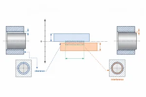
A transition fit sits between clearance and interference. The tolerance zones overlap, which means the same fit designation can produce a small gap or a slight overlap depending on the actual machined sizes.
- Precision location: the tolerance zones overlap within a narrow band, giving accurate positioning without free play
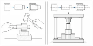
- Easy assembly: parts assemble by hand with light force or a rubber mallet
- Serviceable: normal disassembly does not damage the parts
- Load limit: the joint maintains contact but is not designed for high torque or heavy load transfer
This is why a transition fit is the standard answer for locating pins and alignment features rather than for power transmission.
When to Use a Transition Fit
Transition fits are chosen when a component must be positioned precisely but still be assembled and disassembled without force. The same logic appears in bearing selection: an interference fit locks a bearing in place, a clearance fit lets it slide, and a transition fit is used when the assembly needs moderate force and moderate security. Common applications:
- Locating pins and alignment pins that line up two parts
- Gear hubs and precision pulleys that need accurate location and service access
- Bearing and sleeve assemblies that balance retention with moderate assembly force
- Precision components that are disassembled regularly for maintenance
Assembly typically uses a light press or a rubber mallet. If the joint has to transmit high torque or carry heavy loads, an interference fit is the safer choice.
Tolerances and ISO Codes: How to Specify a Transition Fit
On drawings, a fit is written as an alphanumeric code: the capital letter and number define the hole (for example H7), and the lowercase letter and number define the shaft (for example k6). The number is the ISO 286 tolerance grade; the letter sets the position of the tolerance zone. H7/k6 is the common transition-fit combination.
| Code | Fit Type | Result at 25mm | Typical Use |
|---|---|---|---|
| H7/k6 | Transition | Minimum clearance or slight interference | Locating pins, gear hubs |
| H7/g6 | Clearance | 0.007–0.041mm clearance | Machine tool slides |
| H7/h6 | Locational clearance | 0–0.034mm clearance | Dowel pins, alignment holes |
| H7/p6 | Interference | Always overlapping | Permanent connections |
Fits are specified on a hole-basis or shaft-basis system: hole-basis keeps the hole fixed and adjusts the shaft (the common choice), while shaft-basis does the opposite. The tolerance grade is also a manufacturing decision. An H7 hole is a standard choice because it can be produced with high-quality reamers, while shafts at IT grades 6 and 7 are typically turned and then ground; each additional step raises machining cost. Tighter tolerances increase cost, so specify the loosest fit that still meets the function.
How to Choose the Right Fit
Choose by function, not by habit. Material and temperature belong in the check as well, because aluminum and steel expand at different rates and a fit that works at room temperature can bind or loosen in service. Work through these checks:
- Movement: does the part need to slide or rotate? Use a clearance fit
- Location: does it need precise positioning with service access? Use a transition fit
- Load: does the joint carry high load permanently? Use an interference fit
- Assembly: can the shop press or heat parts? Interference needs it; transition does not
- Cost: tighter tolerances cost more; loosen the fit when function allows
- Standard: specify the fit with ISO 286 or ASME B4.1 codes on the drawing
- Watch for: too tight creates stress and assembly problems; too loose causes movement and wear
Conclusion
A transition fit is the middle ground between clearance and interference. Its tolerance zones overlap, so it delivers precise location with light-force assembly and clean disassembly. Specify it with an ISO code such as H7/k6, and confirm the tolerance grade, assembly method, and inspection capability with the machine shop before production.
FAQ
What is a transition fit?
A fit where the hole and shaft tolerance zones overlap, so the assembled pair may have a small clearance or slight interference depending on actual dimensions.
When should you use a transition fit?
When a part needs precise location but still must be assembled and disassembled without force, such as locating pins, gear hubs, and precision pulleys.
How does a transition fit differ from an interference fit?
An interference fit always overlaps and requires pressing or heating for a permanent joint; a transition fit may overlap or clear and assembles with light force.
How do you specify a transition fit on a drawing?
Write the hole code and shaft code, for example H7/k6, where H7 is the hole tolerance class and k6 is the shaft tolerance class under ISO 286.
Can a transition fit be disassembled?
Yes. Normal disassembly does not damage the parts, which is one of the main reasons to choose it over an interference fit.