Text milling is a common method for adding long-lasting identification to CNC parts, such as part numbers, serial numbers, and brand logos. By using a rotating cutting tool, it creates physical depth on the workpiece surface, making the mark more suitable for parts that need to remain readable after machining, handling, or surface finishing.
Unlike printing, labeling, or shallow surface marking, text milling removes material to form recessed text. The final result depends on factors such as font structure, tool geometry, material properties, milled depth, and the sequence of surface finishing. This guide covers how text milling works, the role of CAM and G-code, and the essential design rules for selecting fonts, tools, and materials.
What is Text Milling?
Text milling is a CNC machining process where a rotating cutting tool removes material from a part’s surface to form characters, symbols, or logos. It is commonly used for part identification, such as serial numbers, batch codes, orientation arrows, or brand marks.
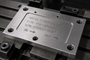
Unlike surface marking methods such as printing, labeling, or laser marking, text milling creates physical grooves or measurable depth. Because the marking is not merely a surface color change, it is suitable for industrial parts that require long-lasting legibility, wear resistance, and traceability.
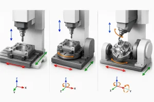
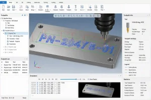
How Does CNC Text Milling Work?
The workflow for text milling translates design specifications into machining operations. The process moves from initial documentation to precise material removal.
Preparing Text Content and CAD Geometry
Identification requirements are typically defined in engineering drawings or project specifications. Designers must specify the text content, location, orientation, character height, and the engraving area. In the CAD phase, text is converted into machinable geometry, such as closed contours or centerlines, ensuring the data is ready for toolpath generation.
Generating Toolpaths and G-Code
CAM software calculates paths based on the text geometry, tooling, material, and target milled depth. The software outputs G-code, which directs the CNC machine’s spindle and axes. This code governs the tool’s movement, including plunge depth, retraction, and feed rates to achieve precise material removal.
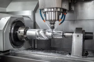
CNC Machining, Deburring, and Inspection
The CNC machine executes the toolpath to cut the text into the workpiece. Because small characters and deep channels can generate metal burrs, deburring is a standard post-machining step. Final inspection involves verifying the milled depth, edge quality, and overall position against the drawing requirements.
The CAM Process: From Text to G-Code
The CAM stage converts 2D text into toolpaths with defined cutter motion and depth. This step determines whether the final text can be machined clearly and consistently.
Text and Logo File Preparation
Text and logos are best provided as vector files, such as DXF, SVG, or AI. For broader manufacturing projects, choosing the right CAD file format also helps reduce data conversion issues before machining. Bitmap files (JPG, PNG) cannot be used directly for high-quality toolpaths and require vectorization. Furthermore, logos with fine lines, sharp corners, or complex decorative elements should be simplified to allow the CAM system to recognize continuous, machinable paths.
Common Text Toolpath Types
-
Centerline toolpath: Ideal for single-line fonts and fine text; paths are short, often resulting in shorter machining times.
-
Profile toolpath: Follows the outline of the text; suitable for standard fonts and logo boundaries.
-
Pocketing toolpath: Removes material from the inside of characters; suitable for bold text, large logos, or filled-in identifiers.
CNC Engraving Software and G-Code Output
Software such as Fusion 360, Mastercam, SolidWorks CAM, VCarve, or F-Engrave is used to convert vector text into programs tailored to specific machines. Customers generally do not need to provide G-code. Providing the text content, location, target depth, material, and vector files is sufficient, as the machine shop will verify the program based on their specific tooling and machine configuration.
For custom CNC parts that require part numbers, serial numbers, logos, or functional markings, Minghe can review the drawing, marking position, material, and finishing requirements together with the overall CNC machining process.
Fonts for CNC Text Milling
Font selection affects path complexity, machining time, burr risk, and legibility.
-
Single-line fonts: Designed for centerline milling; paths are simple and efficient.
-
Sans-serif fonts: Clean, stable line work; a common choice for industrial identifiers.
-
Monospaced fonts: Ensures fixed spacing; useful for aligning serial or batch numbers.
-
Decorative or custom fonts: Often feature complex details and sharp angles, which may increase the risk of burrs, tool breakage, or poor legibility.
CNC Text Milling Design Rules
Adhering to DFM (Design for Manufacturability) principles helps reduce machining risk and improves marking clarity.
Text Size, Stroke Width, and Engraving Depth
Character height and stroke width should be balanced with the tool diameter. For profile milling or pocketing, the stroke width should be wider than the tool diameter. For single-line fonts or V-bit tools, the width depends on the tool angle and the target depth. A typical milled depth is 0.1–0.3 mm; deeper milling increases tool load and burr risk, while shallower milling may lose definition after finishing.
Text Placement and Functional Surface Avoidance
Text should generally avoid sealing surfaces, bearing seats, precision mating surfaces, sliding areas, thin-walled sections, and high-stress concentrations. Deep marking can affect assembly precision, sealing performance, friction, and fatigue strength. For small or thin-walled parts, verify that the engraving area has sufficient material thickness.
Recessed Text, Raised Text, Logo, and Surface Finishing
Recessed text is the most common and cost-effective method. Raised text requires removing the surrounding background material, which increases machining time and cost. Logos should be simplified to remove unnecessary fine detail. Regarding surface finishing, milling the text before finishing can help maintain coating consistency. Milling after finishing may provide higher visual contrast, but it can also expose the base material and affect corrosion protection.
Tooling and Cutting Strategies

Tool selection depends on font size, material, target depth, and machine rigidity.
| Tool Type | Suitable Use | Notes |
| V-bit Cutter | Small text, centerline, fine lines | Line width affected by angle/depth; tip is fragile |
| Small End Mill | Profile text, pocketing, logos | Requires adequate rigidity and chip clearance |
| Ball End Mill | Curved surfaces, shallow marks | Smooth bottom transition; less sharp edges |
| Single-flute Cutter | Aluminum, plastic | Good for light cuts; requires vibration control |
| Diamond Drag Tool | Hard surface scratch marking | For scratching, not for deep milling |
Tooling is a balance of precision and cost. Small diameter tools are prone to breakage, and deeper milling requires more conservative feed and speed parameters.
Materials for CNC Text Milling
Aluminum alloys are commonly used for text milling, offering clear marking, low cutting resistance, and relatively easy burr removal.
Stainless steel and carbon steel provide high durability but, due to their hardness, require conservative machining parameters to reduce tool wear and manage burrs.
Brass and copper can produce clean marks, but their softer cutting behavior may cause burrs or curled edges, requiring a dedicated deburring step.
Engineering plastics require careful control of spindle speed and feed rate to avoid melting, material white-out, tool adhesion, or smeared edges.
Text Milling vs. Other Identification Methods
| Method | Marking Depth | Durability | Suitable Use | Limitations |
| Text milling / milled text | Physical depth | High | Wear-resistant marks and long-term traceability | Higher cost and machining time |
| Shallow CNC engraving | Shallow to medium | High | Nameplates, decorative marks, and light text | Depth and contour are limited by tool geometry |
| Laser marking | Very shallow or surface-level change | Medium to high | Serial numbers, QR codes, and high-volume marking | Not suitable when physical depth is required |
| Printing | No cutting depth | Low | High-volume visual labeling | Can wear off or be affected by cleaning |
| Labels | No cutting depth | Low | Temporary marking and inventory control | Can peel off or fail in harsh environments |
Text milling is suitable when physical depth, wear resistance, and long-term readability are required. For small serial numbers, QR codes, or high-volume surface marking, laser marking is often more efficient.
Best Practices for Text Milling
Use this checklist when designing and requesting a quote:
-
Use simple fonts.
-
Provide vector files (DXF/SVG/AI).
-
Match character height, stroke width, and tool size.
-
Explicitly indicate target milled depth.
-
Avoid sealing surfaces, bearing seats, thin-walled areas, and high-stress zones.
-
Confirm the surface finishing sequence in advance.
-
Perform CAM simulation or prototype verification for small text or curved surfaces.
FAQs About CNC Text Milling
How deep can CNC text be milled?
Typical milled depths are evaluated in the 0.1–0.5 mm range, depending on material and text size. Deeper milling increases machining time, burr formation, and tool breakage risk.
Should text milling be done before or after surface finishing?
It depends on aesthetics, corrosion resistance, and readability. Milling the text before finishing keeps coating consistent, while milling after finishing may provide higher contrast, though it can also expose the base material and affect corrosion protection.
Why is the text blurry or inconsistent in depth after machining?
This is typically caused by overly thin fonts, tool wear, mismatched tool radii, inappropriate machining parameters, uneven clamping, or surface finish covering the detail.
Conclusion
Text milling is suitable for CNC identification that requires physical depth, wear resistance, and long-term readability. Design projects by confirming fonts, depth, tooling, materials, surface finishing, and file formats in advance to balance marking requirements with machining efficiency.